IFR
- Enroute Clearance
- SID - Standard Instrument Departure
- CPDLC
- Classification of Instrument Approaches
- Slots
- Visual Departure
- Visual Approach
Enroute Clearance
The enroute clearance, often also called IFR clearance, is usually the first clearance that an air traffic controller gives to any departing IFR pilot. As the name suggests, it contains important instructions for the flight route the pilot is cleared for.
Fortunately, the structure of an enroute clearance is always the same. It consists of the following elements:
- Clearance Limit
- Departure route
- Clearance of the route
- Initial Climb
- Transponder code
These elements will be explained in more detail below, followed by phraseological examples at the end.
Clearance Limit
The so-called clearance limit indicates the waypoint / airport up to which the enroute clearance is valid.
At this point, we briefly need to talk about different flight plans. While IFR and VFR are commonly known, the two more exotic flight plan types Y and Z are mostly unknown.
Flugpläne
|
I |
IFR flight plan |
|
| V |
VFR flight plan |
|
| Z |
ZULU flight plan VFR -> IFR |
|
| Y |
YANKEE flight plan IFR -> VFR |
|
But why is all this in the Clearance Limit section?
With IFR flight plans, the pilot flies completely IFR up to the destination airport, which is why the IFR route clearance must also extend to the destination airport. The clearance limit for IFR flight plans is therefore always the destination airport.
With Y flight plans, however, the pilot only flies IFR up to a waypoint, VOR, NDB, etc. IFR. The clearance limit for Y flight plans is therefore not the destination airport, but the last waypoint before the pilot switches to VFR according to the flight plan
Phraseology
CLEARED TO NÜRNBERG
CLEARED TO UPALA
Departure Route
In the second part of the IFR route clearance, the pilot is told which departure route to take off on. There are several possibilities for that:
Standard Instrument Departure (SID)
The SID is the most common and probably best-known departure procedure for instrument flights. A valid flight plan always contains the end point of a SID as the first waypoint like for example AKANU in Nuremberg and MERSI in Munich. From this point onwards, the pilot has various airways and waypoints listed in the flight plan that will ultimately take them to the destination aerodrome. If the airways are regarded as highways, the SIDs would be the highway access points, i.e. routes from a connection point (airfield) to the highways (airways). The published SIDs depend on the airport’s operating direction and contain information on flight direction, altitude and speeds. An easy way to access the corresponding charts is offered by the provider Chartfox, where you can easily log in with your VATSIM account. Follow this link and take a look at the departure routes of runway 26R in Munich for the MIQ, GIVMI and RIDAR waypoints.
Omnidirectional Instrument Departure (OID)
The OID is becoming increasingly common in Germany. It is regularly used at military airfields (where it is sometimes called "Operational Instrument Departure"), but more and more OIDs are also being implemented at civil airports.
Unlike SIDs (Standard Instrument Departures), OIDs do not end at specific waypoints but consist of one or more headings without a defined endpoint - often simply the runway heading. Therefore, the aircraft on an OID must receive instructions or radar vectors to the first enroute waypoint.
The main reason for the increase in OIDs is an EU regulation requiring all member states to convert their primary flight procedures to PBN (Performance-Based Navigation) procedures, which essentially means RNAV and RNP procedures. As a result, conventional SIDs based on VORs and NDBs will become increasingly rare. However, some aircraft are not RNAV-capable and therefore require an alternative—such as an OID. For this reason, OIDs often include the remark: "For Non-RNAV-1 equipped aircraft only."
An OID usually has to be coordinated between the delivery controller and the radar controller. Details can be found in the SOPs of the respective airport.
OIDs generally follow a specific naming convention:
-
At civilian airports, they include the airport’s four-letter ICAO code, followed by a sequential validity indicator (1-9) and a letter for identification - often E/W/N/S representing East, West, North, or South (e.g., Leipzig: "EDDP1E").
-
At military airfields, they typically consist of the last two letters of the ICAO code, a digit from 1-9, followed by the runway designation (e.g., Nörvenich (ETNN): "NN124").
Unlike a Vectored Departure, an OID is a published and clearly defined departure procedure that has been assessed for obstacle clearance, is published in charts, and is included in FMS databases.
OIDs also differ slightly from traditional SIDs in terms of phraseology - see the Phraseology section for details.
Vectored Departure
Sometimes it is not possible to assign a SID. There can be various reasons for this: Some airfields require certain aircraft equipment (e.g. GPS) for certain departure routes, sometimes the pilot has problems with their FMS and therefore cannot fly the SID. A third reason that occurs from time to time is pilots who want to fly so-called IFR patterns. These are often flown during landing training. After departure from the approach, the pilot is guided to the ILS via vectors and then handed back to the tower. After the touch and go, the pilot is handed back to APP and the game starts all over again. With such procedures, it makes no sense to release the pilot to a SID, as this is designed to bring the pilot into the airway system. With IFR patterns, however, the pilot does not want to go to an airway, but to remain at our airfield.
A vectored departure must ALWAYS be coordinated with Approach or the Center station above. If you control Delivery, the Tower also needs to be informed.
Example of coordination:
EDDN_TWR: Approach, Nürnberg Tower
EDDN_APP: Go ahead
EDDN_TWR: Request vectored departure DLH414 for IFR Pattern
EDDN_APP: Approved, on RWY Heading climb FL070
Phraseology
- SID: The SID is cleared by simply stating the SID’s name and the addition ‘departure’. In the example of the GIVMI departure in Munich from runway 26R:
*VIA* GIVMI1N DEPARTURE
The word via is optional. It is not necessary to specify the runway in this case, as the SID GIVMI1N only starts from runway 26R. If the pilot knows their SID, they therefore also know their runway. However, there are also SIDs that can be flown from several runways (e.g. in Frankfurt for runway 25C/L). In this case, the runway must be defined in the enroute clearance unless the departure runway is obvious due to the ATIS
- OID: The OID is also cleared by stating its name followed by the addition of "Departure." However, between "Departure" and the "flight planned route," additional information is provided on how the pilot should transition to their planned route. Depending on coordination between the delivery and radar controller, this could look something like this:
*VIA* EDDR1W DEPARTURE, EXPECT RADAR VECTORS TO TOMPI, THEREAFTER FLIGHT PLANNED ROUTE
oder
*VIA* EDDH1G DEPARTURE, LEFT TURN TO IDEKO, THEREAFTER FLIGHT PLANNED ROUTE
- Vectored Departure: After Approach has told you how they want the departure, you must pass on the relevant information to the pilot:
*VIA* VECTORED DEPARTURE RWY 28, CLIMB ON RWY HEADING FL70
The tower controller must then also be informed of the vectored departure so that they know where the aircraft is going to fly initially.
Clearance of the route
After the first two items of the clearance, we have told the pilot up to which point their route clearance applies and how they should fly to the first waypoint in the flight plan. What is still missing, however, is how they should fly from the first waypoint or the SID endpoint to the clearance limit.
In many cases, this is supposed to happen via the route filed in the flight plan. We express this with the following speech group:
FLIGHT PLANNED ROUTE.
In rare exceptional cases, the "flight planned route" is not mentioned. There can be various reasons for this, such as:
- Re-Routing: The flight plan submitted by the pilot is nothing more than a literal "plan" or "wish," which the air traffic controller may deviate from (e.g., because the route is not valid or operational reasons necessitate a different routing). One option is therefore to verbally communicate the new route. In such cases, it makes sense to prepare the pilot, for example, with: "I have a rerouting, advise ready to copy."
- Example of a complete re-routing:
"Cleared to Nuremberg via KOMIB3D departure, after KOMIB direct ERTES, thereafter direct DODAS, expect DODAS1V arrival, climb via SID to 4000 ft, squawk 1255" - Example of a partial re-routing
(the pilot originally filed SOBRA2L but cannot meet the climb restriction of the SID):
"Cleared to Washington via ULKIG4L departure, after ULKIG flight planned route, climb via SID to 4000 ft, squawk 4113"
- Example of a complete re-routing:
- The last point of the SID may, on short flights, also be the final waypoint of the entire route.
Example: EDDF - EDDK
"Cleared to Cologne via OBOKA3W departure, climb via SID to FL70, squawk 1243"
→ A "flight planned route" is not necessary here, as the route ends at OBOKA.
Initial Climb
Even if every SID has a permanently assigned initial climb in the charts or in the AIP, since 2020 this has had to be explicitly mentioned in every IFR enroute clearance. The initial climb is the altitude up to which the pilot may climb independently after take-off without further clearance.
There are, however, two different versions of this speech group:
There are SIDs that have neither altitude nor speed limits. Here we use:
CLIMB TO *ALTITUDE* 5000 FT
There are SIDs that have either altitude or speed limits or both. Here we use:
CLIMB VIA SID TO *ALTITUDE* 5000 FT
In the case of a vectored departure, this speech group is omitted, as the altitude instruction is already given when the flight route is communicated (e.g. ON RWY HEADING CLIMB TO FL70).
The word Altitude or Flight Level is optional. However, it is recommended, especially in the case of altitude, to avoid misunderstandings with the "to" ("Climb to four thousand feet" vs. "Climb two four thousand feet").
Transponder code
Last, but not least, the transponder code. The purpose of this is to uniquely identify an aircraft on radar.
The transponder code is simply added after the word SQUAWK, e.g.
SQUAWK 2001
Each digit is pronounced individually, unless the transponder code consists of full thousands. In this case, the code must be pronounced as follows: SQUAWK 1000 = SQUAWK ONE TOUSAND.
Phraseology examples
If we bring these items together we can create our first IFR enroute clearance.
As an example, let’s assume a flight from Nuremberg to Munich with the route AKANU from runway 28. The transponder code is 1000. We assume that there is little traffic and therefore also issue the startup clearance. The callsign is DLH414.
The complete transmission is:
DLH414, STARTUP APPROVED, CLEARED TO MÜNCHEN, *VIA* AKANU8K DEPARTURE, FLIGHT PLANNED ROUTE, CLIMB TO FL70, SQUAWK 1000, (additional information or instructions)
The words printed in bold are always the same, the words in normal print must be adapted to the respective flight.
The phraseology for a Vectored Departure is:
DLH414, STARTUP APPROVED, CLEARED TO MÜNCHEN, *VIA* VECTORED DEPARTURE RUNWAY 28, CLIMB ON RWY HEADING TO FL70, FLIGHT PLANNED ROUTE, SQUAWK 1000, when airborne contact München Radar 129.525.
SID - Standard Instrument Departure
In order to connect airports with the airway system for IFR flights, predefined departure routes (Standard Instrument Departure - SID) are used. These lead from the respective runway via waypoints and/or conventional navigation facilities such as NDBs and VORs to the first waypoint entered in the flight plan. Nowadays, many SIDs can no longer be flown using conventional radio navigation equipment, as flight routes are becoming increasingly complex, particularly due to noise abatement measures. Their waypoints usually only exist as virtual coordinates. In many cases, therefore, area navigation (RNAV) equipment is required, which every modern airliner is equipped with.
The name of a SID consists of:
- Basic Indicator: Last waypoint of a SID or first waypoint in the flight plan
- Validity Indicator: The Validity Indicator is a number that is incremented as soon as there are minor changes to a SID (e.g. change of variation)
- Route Indicator: The Route Indicator is a letter that can be used to distinguish between different SIDs that lead to the same waypoint. These can differ, for example, due to different runways, routings, altitude restrictions, etc. An example is MERSI6N from runway 26R and MERSI5S from runway 26L in Munich, as shown below.
Example for naming: MARUN6M

Route of the MERSI SIDs in Munich
Route
With the clearance of a SID, the following instructions should generally be clear to the pilot:
-
departure runway in conjunction with the ATIS,
-
initial climb clearance
-
route to be flown with possible restrictions (e.g. speeds or altitudes).
-
frequency change after take-off. In Germany, the frequency change after take-off is part of the SID procedure at many airports. You should therefore always check whether you may/should change frequency independently before take-off. In this case, the tower will not give any instructions, as the frequency changes are indicated in the SID and/or ATIS.
This information can be found in the SID or its charts.
Noise Abatement
In Germany, for noise abatement reasons, controllers are only allowed to issue directs or vectors from certain altitudes when departing via a SID. Any speed and/or altitude restrictions may also only be lifted above these altitudes. These altitudes are:
- 5000ft AGL for JET-powered aircraft
- 3000ft AGL for PROP-powered aircraft
CPDLC
 Controller Pilot Data Link Communications (CPDLC) is a two-way data-link system by which controllers can transmit non-urgent 'strategic' messages to an aircraft as an alternative to voice communications. The message is displayed on a flight deck visual display.
CPDLC was first implemented in Europe by Eurocontrol's Maastricht Upper Airspace Control Centre. Since then, many other ANSPs worldwide have implemented CPDLC. Nowadays, most aircraft flying as GAT above FL285 within the Single European Sky (SES) must be CPDLC equipped (with a few exceptions).
In Germany, CPDLC is only available in UACs Maastricht (MUAC) and Karlsruhe (KUAC). ACCs Bremen, Langen and München do not offer CPDLC services.
Benefits and Risks
Multiple studies describe the following benefits of CPDLC:
- Less communication on the ATC frequency
- Increased sector capacities
- More pilot requests can be dealt with simultaneously
- Reduced probability of miscommunication (e.g. due to callsign confusion)
- Safer frequency changes, hence fewer loss of communication events
The following risks can exist:
- Long and complex CPDLC messages resulting in higher workload and/or misinterpretations of ATC clearances
- Wrong messages to an aircraft or transmission of a message to the wrong aircraft
- General misinterpretation of ATC clearances
- Use of CPDLC during time-critical situations, resulting in unsafe traffic situations
- Clearances from two different controllers when establishing voice communications with the new sector while still connected on CPDLC with the previous sector

Click on the picture to see the video on Skybrary
Main Principles of CPDLC
In general, the following main principles exist for the use of CPDLC:
- Voice and data link shall co-exist. Pilots are required to monitor ATC's frequency and have to make an initial call after changing frequencies. Additionally, ATC can always use voice communications when necessary.
- CPDLC shall only be used in the context of non-time-critical communications. Time-criticality is mainly determined by the following factors: ATC traffic situation, end-to-end performance (systems and flight crew/controller response time) and recovery time. Users should be aware that while a voice response is generally expected in a few seconds, the latency of CPDLC is usually much longer (up to several minutes).
- Only one open dialogue of the same type (climb/descent, direct, speed, heading, squawk) with the same aircraft at any given time is allowed. For example, it is not allowed to issue two climb instructions without a response from the pilot between both messages. This is to avoid confusion and misinterpretation of ATC clearances.
- The decision to use either voice or CPDLC shall be at the discretion of the controller and/or pilot involved.
- The provision of CPDLC shall respect the following standard as provided in ICAO Annex 11, Chapter 3, par. 3.5.1: “A controlled flight shall be under the control of only one air traffic control unit at any given time”.
CPDLC Operations
In Germany, CPDLC services will only be provided in the upper airspace (EDYY/EDUU). When covering upper sectors on Vatsim, controllers connected as EDWW, EDGG, or EDMM may choose to provide CPDLC service. In this case, controllers shall only allow CPDLC logons and issue CPDLC messages for aircraft within the upper airspace. For traffic using CPDLC services, CPDLC shall be disconnected by the controller when the aircraft is leaving the upper airspace.
CPDLC can be used for the following messages:
- ATC clearances (level changes incl. vertical rates, vectoring, direct routings, speed control)
- Change of SSR code
- Transfer of control and communication
- Response to CPDLC Free-Text messages
For the Vatsim environment, controllers intending to offer CPDLC services need to use the Hoppies ACARS server. For Vatsim Germany, service will be provided by using the Topsky Plugin, which is implemented in all Euroscope controller packages.
Expand this box to view the CPDLC functions of the Topsky Plugin.
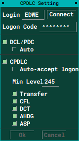
Connect to the Hoppies Server
To connect to the CPDLC server, the controller needs to enter the Hoppies Logon Code and CPDLC Login code of the desired station which can be found here. Usually, the CPDLC Login code is already enter by default. You can save your Hoppies Logon Code in the Topsky directory of the Euroscope controller package (TopSkyCPDLChoppieCode.txt).
CPDLC Current Message Window
The CPDLC Current Message window shows every CPDLC transmission sent between the pilot and controller. Completed CPDLC messages will be automatically deleted after a couple of minutes.

Establish CPDLC Connection to the Pilot
When a pilot requests to establish CPDLC connection, it will be indicated by two flashing square brackets ("[ ]") around the aircraft callsign in the label. Additionally, you will receive a CPDLC message in the Current Message window.
To establish CPDLC connection, the controller must answer the request by clicking on the message in the Current Message window or by using the "Start CPDLC" button in the Topsky Callsign label menu.

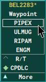
Issuing Clearances
CPDLC clearances can be generated by using Topsky's normal CFL/ASP/Waypoint/Heading windows. To send the CPDLC message, the controller first needs to make sure that "CPDLC" at the bottom of the window is selected. Then the controller just clicks on the desired clearance. When selecting "R/T" (radio transmission) the clearance will just be entered in the label without sending a CPDLC message. This can be particulary useful when the clearance has already been transmitted by voice communications.
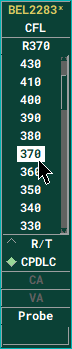
Clearances issued to the pilot will be displayed in squared brackets in the label. Once the pilot confirms the clearance, it will be automatically entered in the label. To transmit vertical rates via CPDLC, the controller must first enter the assigned rate in the label and then selected to desired level in the CFL menu.
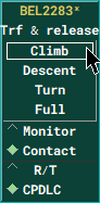
Transfer of Communications
When a pilot needs to be transferred to the next station, the controller can use the "Transfer" or "Transfer and Release" function of Topsky's Callsign menu. Besides the usual "CPDLC" and "R/T" option, there is also a "Monitor" and "Contact" option avilable to choose from. This option enables the controller to chose whether to send a CPDLC message to the pilot instructing to contact or to monitor the next frequency. By default the "Contact" option is selected.
Whenever the next ATC station is also connected to CPDLC, the CPDLC connection will be transferred automatically. Be aware that this function might not work for all aircraft in the simulator.
When intending to send an aicraft to Unicom/Advisory (122.800) the Free-Text option, which can be found in Topsky's callsign menu, needs to be used. When using this message, the aircraft's label will be automatically released once the CPDLC message is answered by the pilot. Additionally, the CPDLC connection will be terminated.
CPDLC Free Text
Besides the Unicom/Advisory message, there are multiple other CPDLC free text messages available. This section is highly individual. Please your Euroscope controller package's manual for further information.
Topsky Datalink Manual
Further information about Topsky's CPDLC functions can be found in the documentation folder of your Topsky directory of the Euroscope controller package.
Reverting to Voice
Usually, when a controller or pilot communicates via CPDLC, the response should be via CPDLC. When a controller or pilot communicates via voice, the response should be via voice. The following circumstances describe potential situations where the air-ground communications should revert to voice:
- When it is required to clarify the meaning or the intent of any CPDLC message
- When it is necessary to ensure the timely execution of an instruction issued by CPDLC
- When corrective actions are required with respect to unintended messages that have been sent using CPDLC
- When a system generates a time-out or an error for a CPDLC message
CPDLC Related Phraseology
The following phraseology regarding the use of CPDLC is defined in the AIP:
| Deutsch | English |
| Failure of CPDLC | |
| [AN ALLE FUNKSTELLEN] CPDLC Ausfall (Anweisungen) | [ALL STATIONS] CPDLC FAILURE (instructions) |
| Failure of a single CPDLC message | |
| CPDLC NACHRICHTEN FEHLER (angemessene Freigabe, Anweisung, Information oder Anfrage); | CPDLC MESSAGE FAILURE (appropriate clearance, instruction, information or request) |
| To correct CPDLC clearances, instructions, information or requests | |
| IGNORIEREN SIE CPDLC (Art der Nachricht) NACHRICHT, TRENNUNG (korrigierte Freigabe, Anweisung, Information oder Anfrage) | DISREGARD CPDLC (message type) MESSAGE, BREAK (correct clearance, instruction, information or request); |
| To instruct all stations or a specific flight to avoid sending CPDLC requests for a limited period of time | |
| [AN ALLE FUNKSTELLEN] [BIS AUF WEITERES] KEINE CPDLC ANFRAGEN MEHR SENDEN [(Gründe)] | [ALL STATIONS] STOP SENDING CPDLC REQUESTS [UNTIL ADVISED] [(reason)] |
| To resume normal use of CPDLC | |
| [AN ALLE FUNKSTELLEN] NEHMEN SIE DEN NORMALEN CPDLC-BETRIEB WIEDER AUF | [ALL STATIONS] RESUME NORMAL CPDLC OPERATIONS |
Source: www.skybrary.aero
Classification of Instrument Approaches
Segment of an instrument approach
Arrival Segment: This segment represents a transition from the enroute phase to the approach phase of the flight.
Initial Approach Segment: This segment begins with the Initial Approach Fix (IAF) and ends at the Intermediate Fix (IF)
Intermediate Approach Segment: This segment usually begins at the Intermediate Fix (IF) and ends at the Final Approach Fix (FAF) (non-precision) or Final Approach Point (FAP) (precision).
Final Approach Segment: This segment normally starts at the FAF/FAP and ends at the Missed Approach Point (MAPt).
Missed Approach Segment: This segment begins at the MAPt and usually ends in the published holding procedure at the IAF. It is intended to provide protection against obstacles during the entire missed approach procedure.
Final Approach Fix or Point? During a Precision Approach, it is called a Final Approach Point, during a non-precision approach, it is called a Final Approach Fix.
Classification
There are several ways to conduct approaches under instrument flight rules.
The purpose of the various approaches is to guide traffic to the runway as efficiently and precisely as possible in line with local circumstances and depending on weather conditions. Some approaches require specific equipment on the ground, while others are solely dependent on the aircraft's equipment. All available approaches are published in the respective airport charts.
In addition to the larger commercial airports, various small airports with an RMZ also have such approach procedures to enable IFR traffic there.
A basic distinction is made between two-dimensional (2D) and three-dimensional (3D) approach procedures.
2D approach procedures only include lateral guidance, while 3D approach procedures also include vertical guidance.
Note: lateral and vertical refers to the guidance provided by either:
- a ground-based radio navigation aid or
- computer-generated navigation data from ground-based, space-based, autonomous navigation aids or a combination of these.
Examples of 2D approach procedures:
- LOC Approach (Non-precision approach (NPA))
- VOR approach (NPA)
- NDB Approach (NPA)
- RNP Approach (RNAV(GPS)) without vertical guidance (NPA)
Examples of 3D approach procedures:
Note: Visual approaches do not belong to any of these categories!
ILS approach
The ILS approach is the most widely used approach procedure in Germany and accurate enough to be considered a precision approach. ILS stands for Instrument Landing System and consists of a landing course transmitter (LOC - shows the deviation to the left and right of the extended centerline) and a glide path transmitter (GS - shows the deviation from the ideal altitude for the approach). The combination of these two components guides the pilot precisely onto the runway, even in poor weather conditions, and in some cases also enables completely automatic landings. In order to use this approach procedure, the airport must be equipped accordingly.
VOR approach
Sometimes no ILS/RNAV is available at the destination airport or the expected runway. A somewhat outdated method is the VOR/(DME) approach. This approach is considered a non-precision approach as well.
The challenge here is that the pilot aims at a fixed radio navigation station on the ground and follows its radial.
It is important for the controller to know that this approach procedure is rather imprecise compared to the ILS. The pilot might deviate noticeably to the left or right of the extended centerline. They fly the approach to the missed approach point (MAPt) or until the runway is in sight. As there is no vertical guidance for this approach, the decision height is relatively high. It is therefore not worth flying a VOR approach in bad weather.
NDB Anflug
The NDB approach is the last point in the approach list. This approach is by far the least accurate and therefore also classified as a non-precision approach. In contrast to a VOR, which transmits a clear radial, the NDB transmits signals in all directions simultaneously. With a VOR approach, the pilot recognizes directly whether he is correctly aligned. This is not very easy with the NDB approach due to its inaccuracy.
Alignment to the extended centerline of the runway is not based on a radial, but on a QDR (magnetic bearing from the station) transmitted by the station. The descent is started from a defined point and is similar to the VOR approach, as there is no vertical guidance here either.
Vectoring to Final
-
During a precision approach, the pilot should fly straight and level for 1 NM before intercepting the glide slope. E.g. FAP at 10 NM -> glide slope intercept at 11 NM
-
With an RNP or RNAV(GPS) approach, the pilot shall fly straight and level for 2NM before passing the final approach fix. E.g. FAF at 12 NM -> intercept at 14 NM
-
If the RNP or RNAV(GPS) approach includes a course change at the FAF, the pilot should be cleared directly to a waypoint on the initial approach. E.G. RNP X RWY 25L (EDDF)
-
For NPAs, the pilot must be given information about their position when they are guided to the final approach by vectors. E.g. "DLH123, you are 15 NM southwest of FFM VOR, cleared VOR Approach runway 25L"
-
If an aircraft is vectored to the intercept of the final approach, the pilot must be instructed to report "established". "DLH123, cleared ILS approach runway 25L, report established." This does not apply if an independent feeder is used.
Visual approach
Frequently requested in good weather conditions: The visual approach. Although there are many airports in real life where such an approach is no longer permitted for noise protection reasons, it could certainly be used more often on the VATSIM network. This is not a flight rule change, so the aircraft is not VFR, but on a visual approach for IFR traffic.
Requirements
The following conditions must be met for a visual approach to be carried out:
-
Pilot requests or accepts the Visual Approach
-
Aircraft is below the ceiling, which is above the MVA or the pilot confirms that the visibility conditions are sufficient for the approach
-
Pilot has the airport and the traffic ahead in sight
A visual approach must always be coordinated with the tower.
Clearance
If the above conditions are met, an IFR inbound can be cleared for a visual approach. The pilot is then responsible for obstacle clearance. However, the APP controller is still responsible for the separation.This responsibility can be delegated to the pilot with the remark that the pilot needs to maintain separation to traffic ahead autonomously.
As there is no published missed approach procedure for a visual approach, this must be communicated to the pilot together with the clearance.
| Station | Phraseology |
| ATC | DLH123, Runway is at XX o'clock, Range XX Miles, advise able (to accept) visual approach RWY XX |
| Pilot | DLH123, able (to accept) visual approach RWY XX |
| ATC | DLH123, cleared visual approach Runway XX, in case of missed approach (missed approach procedure) |
Slots
A slot generally refers to a specific time window. In aviation, these are mainly used for times when an aircraft must be in the air or, as a result, when it is allowed to leave its parking position.
Slots are mainly used when there is a high volume of traffic and helps the airport or air traffic controller to continue working as efficiently as possible. Each aircraft or individual aircraft can be allocated certain times.
Departure Slot
VATSIM offers the vACDM tool for certain airports, which takes a lot of the work out of departure control. Details can be found in this book. If the tool is not available or the controller does not use it for some reason, the capacity of the airport must be controlled manually.
For outbounds, this is best controlled via the aircraft's startup clearance. The number of aircraft cleared for startup may not be greater than the airport’s total capacity. All other airplanes must wait their turn accordingly.
An airport with only one runway for take-off and landings has a capacity of around 20 to 30 aircraft movements per hour, depending on the ratio of inbounds to outbounds.
It is important to know the airport's capacity and to recognize the current bottleneck. If, for example, the airport has several independently usable runways and there is only congestion on one of them, it makes little sense for all aircraft to be allocated a slot. Outbounds that can take off from a runway without delay using normal procedures should not have to wait unnecessarily. The same applies to different departure routes, etc.
Queues at the holding point cannot be avoided even with the best systems. How they are processed and which traffic follows them are the most important considerations here.
To maintain an overview, the TSAT (Target Startup Approved Time) should be noted in the scratchpad.
If the workload for a controller and thus the waiting time for the pilots becomes too much, a coordinator can work with the controller on the Delivery position.
Example for 30 outbounds per hour
An airport runway has a capacity of 30 outbounds per hour. On average, this means a departure every 2 minutes. If more than these 30 outbounds want to take off per hour or if they all request the startup clearance at the same time, it is time to act. The easiest way to do this is for Delivery to give startup clearances to outbounds on this runway every 2 minutes. The enroute clearance can also be given in advance, but only at 2-minute intervals startup clearances are issued and the aircraft are sent to ground/apron.
If there is another runway that can be used independently and has free capacity, the 2 minutes do not have to be used for outbounds via this runway.
It is also important for Delivery to have an overview of the holding points. If the holding point threatens to run empty, appropriate countermeasures should be taken and the start release of individual outbounds should be prioritized. The taxi out time for the individual aircraft should also be taken into account! The same applies to a situation where many departures have already been cleared for take-off via the same SID. Here it can be helpful for the tower controller if they can slot additional departures with other departure routes in between in order to reduce the necessary separation.
Visual Departure
General
Most of the IFR flights depart by using an SID. However, this is not the only option. One alternative is a so called visual departure. During this procedure, the pilot is maintaining visual reference to the terrain up to a certain altitude.
A visual departure is despite its name an IFR procedure. Therefore, the tower controller remains responsible for separation according to the airspace class.
There are several reasons why visual departures might be conducted instead of using a SID:
- The procedure is often shorter than a SID - therefore it saves time and fuel
- It may increase departure efficiency for the tower controller
- During significant weather (thunderstorms) in the departure area
- In case of an unexpected outage of a navigational aid for the respective SID
- In case of an unexpected non-availability of all SIDs from the respective runway
Requirements and restrictions
When to apply?
A visual departure may only be permitted if all of the following conditions are met:
- The pilot requests the procedure or accepts the procedure after initiation by ATC
- The weather allows visual reference to the terrain until passing the MVA
- On VATSIM, we assume that this is the case as long as the ceiling is at least as high as the MVA
- The procedure is only allowed during daytime
- The pilot remains responsible for the obstacle clearance until the specified altitude
- ATC remains responsible for separation to all other aircraft according to the airspace class
Unless otherwise stated in the SOPs, visual departures have to be coordinated in advance between Delivery / Tower and the departure controller.
Where to apply?
According to the AIP ENR 1.5, visual departures are allowed at all German airports with IFR procedures.
At certain airports, visual departures may however be restricted due to local regulations (e.g. noise abatement). The restrictions can be found in the SOPs of the respective airport.
However, the local restrictions never apply:
- during significant weather (thunderstorms) in the departure area
- in case of an unexpected outage of a navigational aid for the respective SID
- in case of an unexpected non-availability of all SIDs from the respective runway
Phraseology Examples
The clearance for a visual departure can either be given during the enroute clearance or before the takeoff clearance (this is done e.g. when there is a thunderstorm not allowing to depart on the originally cleared SID).
Example 1: Due to the shorter routing, ATC offers the pilot a visual departure:
ATC: "AZD111, advise able to accept visual departure runway 25L?"
Pilot: "AZD111, able"
ATC: "AZD111, after departure proceed direct SOBRA, climb to 5000 ft, maintain visual reference to the terrain until passing 2500 ft"
Pilot: (readback)
Example 2: The pilot reports on the runway that he needs a heading when airborne due to CBs (that is nothing other than a visual departure):
Pilot: "DLH1312, due to weather request heading 210 when airborne for 15 miles"
ATC: "DLH1312, after departure fly heading 210, maintain visual reference to the terrain until passing 2000 ft"
Pilot: (readback)
ATC: (normal takeoff clearance)
Visual Approach
General
An IFR flight normally ends with an instrument approach to the runway. In addition to the standard approaches (e.g., ILS, GLS, RNP, VOR, NDB), there is another option: the visual approach.
Contrary to popular belief, the visual approach is an IFR procedure - meaning the pilot remains under IFR rules the entire time, and the controller must ensure separation accordingly. The pilot maintains visual contact with the ground during the approach and is responsible for obstacle clearance.
A visual approach may be used for various reasons, such as:
-
Thunderstorms in the approach sector
-
Shortening the approach path in good weather
-
Saving time and fuel
-
-
Unavailability of other instrument approach procedures
-
Failure of onboard aircraft sensors
-
Priority flights (e.g., medical or emergency flights)
-
Visual approaches with runway change on final for shorter taxi times
Requirements and Restrictions
When to apply?
An IFR visual approach may only be cleared if all of the following conditions are met:
-
The visual approach is coordinated between approach and tower controllers
-
The pilot can maintain visual reference with the ground throughout the approach
-
The ceiling (BKN / OVC) is not lower than the beginning of the Initial Approach Segment, or the aircraft is already below the ceiling, or the pilot reports that weather conditions permit a safe visual approach and landing, or the controller suggests the procedure and the pilot accepts under these conditions
In Germany, visual approaches are generally permitted at night.
Additional points to consider:
-
The controller must ensure separation from other traffic according to airspace class, unless delegation is applied (see below)
-
With clearance for a visual approach, the pilot is responsible for obstacle clearance
-
If the pilot previously received radar vectors, the visual approach may only be cleared if the pilot reports the airport or preceding aircraft in sight
-
For runway changes during final, the controller must assign a custom missed approach procedure
A visual approach can be conducted under IMC if the above conditions are met
Where to apply?
According to AIP ENR 1.5, visual approaches are permitted at all German airports with IFR procedures, though often subject to noise abatement restrictions. Details can be found in the AIP and SOPs of the respective airport.
Exception: At airports within an RMZ (Radio Mandatory Zone), visual approaches are generally not permitted.
All local restrictions are generally not applicable:
-
For emergencies
-
During significant weather (e.g., thunderstorms) in the approach sector
-
For flights with STS/HOSP, STS/SAR, STS/FLTCK status
-
In case of unexpected failure of navigation aids for the original instrument approach
-
In case of unexpected unavailability of all instrument approaches
Delegation of Separation
In principle, the controller remains responsible for separation from other traffic in accordance with the airspace class (e.g., from other IFR traffic in Class C, D, and E airspace, and from VFR traffic in Class C).
Exception: Only during daylight, separation to the preceding aircraft may be delegated to the pilot during a visual approach. The pilot is then responsible for maintaining adequate spacing. In this case, radar separation and, if applicable, wake turbulence separation do not apply.
However, if the separation becomes less than the required wake turbulence spacing, a wake turbulence warning must be issued.
Phraseology Examples
Example 1: The pilot is currently able to conduct a visual approach under the above conditions:
Pilot: "Request visual approach runway 25"
ATC: "Cleared visual approach runway 25"
Example 2: The pilot plans a visual approach but cannot yet meet the conditions:
Pilot: "Request vectors for visual approach runway 25"
Once the pilot can meet the conditions:
Pilot: "Able (to accept) visual approach runway 25"
ATC: "Cleared visual approach runway 25"
Example 3: The controller suggests a visual approach:
ATC: "Advise able (to accept) visual approach runway 25"
Pilot: "Able (to accept) visual approach runway 25"
ATC: "Cleared visual approach runway 25"
Example 4: The controller suggests a runway change on final:
ATC: "Advise able (to accept) visual approach runway 25L?"
Pilot: "Able (to accept) visual approach runway 25L"
ATC: "Cleared visual approach runway 25L, in case of missed approach climb on runway track to 5.000 feet"
Example 5: The controller delegates separation to the preceding aircraft:
ATC: "Report Airbus A320 at 10 o'clock position, 5 miles, in sight"
Pilot: "Traffic in sight"
ATC: "Number 2, follow mentioned traffic, maintain own separation, caution wake turbulence"