Approach
- Radar Vectors
- Speeds
- Establishing approach sequences
- Holding Management
- Low Visibility Operations (LVO) - Arrival
Radar Vectors
‘Radar vectors’ just means that an aircraft is guided by the air traffic controller through specific headings. In contrast to a standard IFR procedure (STAR, SID, Standard Approach), a so-called Minimum Vectoring Altitude (MVA) must be adhered to. This is specified for certain precisely defined areas and guarantees an obstacle clearance of at least 500 ft and sufficient radar and radio coverage. The MVA areas can be displayed in Euroscope. Values in brackets apply to the winter months.
Radar vectors can be given as heading (e.g. heading 210) or as relative turn instruction (e.g. right/left by 10 degrees). The latter should only be used if there is not enough time to request a heading. Otherwise, always work with headings.
If a radar vector is not self-explanatory (e.g. for final approach), the reason should always be given (for separation, for spacing, etc.).
Particular care must be taken when an aircraft is in a turn. In this case, requests such as: "Turn left/right by..." are completely pointless, as the aircraft in the turn can not know which heading this instruction refers to! If it is important that the aircraft turns immediately to a specific heading, the following phrase is a good idea:
DLH123 stop turn heading 180
Radar vectors for an ILS approach or localizer should be given with a heading within 30° to the final approach course. Example: Runway direction 26 - Heading for intercept 230° or 290°.
A clearance for an approach does not cancel a previously assigned speed! A new speed assignment must be explicitly communicated to the pilot.
DLH123 resume normal speed, turn right heading 220, cleared ILS 26R.
DLH123 turn right heading 230, cleared ILS 26R, maintain 220 kts to 10NM final thereafter 170 kts until 5 miles final.
The end of a STAR is the IAF, which also includes a holding pattern. This IAF automatically is the clearance limit for the approach unless the clearance limit is specified earlier in the charts.
If the pilot receives no further instructions on what to do before reaching the clearance limit, he must enter the holding pattern. It is therefore a good idea to instruct the pilot on what to do after the last waypoint as soon as the initial contact is made. The clearance to a transition waypoint (e.g. DM427) includes the clearance to continue flying the transition.
DLH123, identified, leave ROKIL on Heading 120, expect ILS 26R.
This prevents the pilots from calling when the frequency load is high and demonstrates good proactive planning!
If you want to turn a departure away from a SID, you must note that for noise protection reasons this is only permitted in Germany above 5000 ft AGL for jets and 3000 ft AGL for props. Below MVA it is totally prohibited.
Tip: A quick note on intercept headings: If strong northerly or southerly winds are known to be present, it is sometimes worth adjusting the course accordingly, i.e. shifting it by 5° or even 10°. Otherwise the pilot flying into the wind may not reach the landing course before the glide path. It makes sense to ask two or three pilots for a wind check at the beginning. Pilots seem to be flying less and less with extremely different winds in recent years (at least it feels like it). It's the exception rather than the rule and requires a little sensitivity in case someone has the wind from somewhere completely different.
Further links
- Skybrary: Basic Controller Techniques - Vectoring
- Skybrary: Vectoring Geometry
- Skybrary: Conflict Solving
- Skybrary: Basic Controller Techniques - Vertical Speed
Speeds
Used sensibly, speed control is a very helpful tool for separating aircraft and maintaining sequences.
Types of speeds
A distinction is made in aviation between different speeds:
- IAS (indicated airspeed):
The speed displayed to the pilot on the airspeed indicator. It is decisive for the aerodynamic behavior of the aircraft, i.e. how many air molecules actually flow around the wing and generate lift. In powered flight, it is generally indicated in KIAS (knots indicated airspeed) (kts=NM/h)
- TAS (true airspeed):
The speed actually flown, i.e. the relative speed of the aircraft in relation to the surrounding (still) air. The discrepancy between IAS and TAS therefore increases as an aircraft flies higher, as the air becomes thinner and thinner and the aircraft must fly faster and faster in relation to the TAS so that the IAS remains constant, i.e. the same amount of air molecules flow around the wing per unit of time. It is specified in KTAS (knots true airspeed). - GS (Ground Speed):
The speed of the vertical projection of the aircraft onto the earth's surface. This is therefore the TAS with the wind influences factored in, which cause the aircraft to fly slower over ground than the TAS if there is a headwind and faster if there is a tailwind. This is the speed displayed to the controller on the radar. - Mach Number:
Percentage of the speed of sound. Indicated with a dot and the percentage, e.g. "Mach .80" = 80% of the speed of sound. The Mach Number depends on many values, such as air density and temperature.
Similar to the rule of thumb for descents (1000 ft in 3 NM), speed reduction is approximately 10 kts in 1 NM.
Using the different speeds
Below FL280, the Indicated Airspeed (IAS) is used, as it is responsible for the aircraft’s aerodynamic behavior.
Above FL280, the Mach number is generally used, as the aircraft then become so fast that the upper limit of the possible speed is no longer determined solely by aerodynamic aspects, but also by the so-called "critical Mach number". This is the Mach number at which the first effects of supersonic air flow occur on the aircraft, causing not only turbulence but also decreasing controllability of the control surfaces. The higher the aircraft climbs, the lower its maximum IAS becomes, while the Mach number remains the same.
If speed control is used for descending aircraft, IAS can and must be used above FL280, which might easily happen at e.g. FL340.
Depending on the aircraft type, the "switching altitude" between IAS/mach/IAS can also be above or below FL280.
A change of Mach 0.01 causes a change in TAS of about 6 kts.
If necessary, the following phraseology can also be used. However, you must be aware that not every pilot will understand this instruction!
DLH123 maintain Mach decimal 80, on conversion 320 knots
Some example values at which FL is switched from IAS to Mach:
| Mach | IAS | Conversion FL |
|---|---|---|
| .82 | 310 | FL303 |
| .82 | 280 | FL350 |
| .82 | 250 | FL399 |
| .78 | 310 | FL278 |
| .78 | 280 | FL324 |
| .78 | 250 | FL374 |
| .74 | 310 | FL250 |
| .74 | 280 | FL299 |
| .74 | 250 | FL350 |
Calculations
Rules of Thumb
0.01M difference~ 6 KT GS
1000ft altitude difference ~ 6 KT GS (The higher the faster)
1 KT GS = 1 NM per hour
60 KT GS = 1 NM per minute
Distance at a certain point
Additional distance = Additional distance between 2 aircraft in NM
m = 60 minutes / flight time to the point at which the distance should exist
Additional distance * m = Speed Delta in KT
Speed Delta in Mach = Speed Delta in KT / 6
A detailed explanation of the rules of thumb is available as a video here.
Example
We have aircraft A and aircraft B at the same altitude, both leaving the sector at point P.
Aircraft A still has 150 NM (20 minutes) to point P.
Aircraft B still has 146 NM (19 minutes) to point P.
We want a separation of at least 7nm at point P. We already have a separation of 4nm, so we need to achieve a separation of an additional 3 NM (7 NM we want minus 4 NM we already have) in 20 minutes.
Now we calculate how many kts GS difference we need between the planes to reach this distance.
Since the speeds are per hour, we now extrapolate this to 60 minutes.
60 minutes / 20 minutes = 3
3 NM spacing * 3 = 9 NM spacing
Since we know that 1 KT GS = 1 NM per hour, we now know that we need a speed difference of 9 KT GS to achieve a distance of 3 NM in 20 minutes
We know 0.01M ~ 6 KT GS, so in this case we need a Mach difference of 0.02M, which will be a difference of 12 KT GS, this will lead to 4nm more difference in 20 minutes, therefore leading to a total of 8 NM (4 NM current distance + 4 NM new distance due to speed difference) distance at point P. If the aircraft are not at the same altitude, we must subtract 6 KT per 1000ft from the speed delta if the higher aircraft is the leading one. If the higher plane is following, we have to add 6 KT per 1000ft to the speed delta.
Distance after a certain time
If speed control is used, the distance after a certain time can easily be calculated:
Spacing = Speed difference / 60 per minute
As a rule of thumb, a speed difference of 30 KT (e.g. 250 KT and 280 KT) over a distance of 30 NM gives a spacing of about 3 - 3.5 NM.
Example
If the preceeding aircraft flies 30 KIAS more than the suceeding, this results in a spacing increase of half a NM per minute! Be careful if the preceedingaircraft is significantly higher than the suceeding! Remember that the TAS decreases the lower the aircraft flies. It is therefore possible that the suceeding aircraft is already flying 30 KIAS slower than the preceeding aircraft, but is still faster in relation to the GS, precisely because it is higher. It is therefore a good tactic to bring the aircraft that you want to fly slowly to the desired altitude first and then reduce the speed. If you want to maintain a high rate of descent, it is of course difficult to radically reduce speed. This should be taken into account!
When approaching an airport and holding is expected, the phrase "Reduce Minimum Clean Speed" is often used, i.e. the request to reduce to the lowest possible speed without setting the flaps. It should be noted that such a speed can always vary depending on the aircraft type and load. It can therefore not be used as a basis for relaying. The phrase "Reduce Minimum Approach Speed" should not be used!
The following rule applies on the final: On the way to the 10 NM final point, approx. 1 NM spacing is lost because the front aircraft reduces earlier. The same applies at the outer marker. You should therefore aim for minimum separation + 2 NM when vectoring so that the separation remains sufficient until touchdown!
Advanced: Ground speed effect
First of all, we need to take a look at the different speeds. The pilot has his indicated airspeed (IAS). The controller has the groundspeed (GS). The connecting element is the true airspeed (TAS). The IAS is only an indicator of how fast the aircraft is currently moving through the air. The GS is an indicator of how fast the aircraft is moving relative to the ground, corrected for influences like air density, wind, etc. This speed corresponds exactly to the speed a car would have on the ground. The TAS is a bit tricky. It expresses the speed that a solid body has in a certain medium. If we ignore the wind , we only have to deal with the solid body (our aircraft) and the medium (air) in which it is moving. At high altitudes, the air becomes thinner. This means less resistance from the medium, which leads to a higher speed of the solid body. The conclusion: the higher the aircraft, the greater the speed. These speeds are all interrelated. The TAS can be determined using a simple formula. The groundspeed is known to the controller, the indicated airspeed must be requested from the pilot.
TAS = IAS + FL / 2
Example
Let's assume that approach has received two aircraft as a package from center. Both are on the same STAR at different altitudes and there is not enough space to separate the aircraft laterally.
Our scenario is as follows: DLH123 at FL150 / 300 KIAS - CFG999 at FL160 / 300 KIAS, same lateral position, same flight direction. We now need them both at 5000ft and 3NM separation within 40NM using vertical techniques only. We assume that there is no wind, so GS = TAS
TAS DLH123 = 300 KT + 150 / 2 = 375 KT TAS
CFG999 = 300 KT + 160 / 2 = 380 KT
We need both aircraft at 5000 ft, so for DLH123:
TAS DLH123 = 300 KT + 50 / 2 = 325 KT
This leads to a speed difference between the aircraft of 55 KT (380 KT - 325 KT), so that the lateral separation increases by about 1 NM per minute (55 KT / 60 minutes).
We therefore need three minutes to separate the aircraft at the speed difference of 3 NM. We must let both aircraft descend simultaneously and one must reach our target fix three minutes before the other. What must the descent rates be in order to achieve this?
First, we calculate the descend rate of the higher aircraft. This moves at 380 KTS GS. It needs approx. 6 minutes for the 40 NM (40 NM / (380 KT / 60 minutes)) and must lose 10,000ft. This leads to a sink rate of 1700 ft/m.
DLH123 also needs 6 minutes at its current altitude and speed, but has to be there 3 minutes later than the higher CFG999. So it has to lose the 11,000ft in 3 minutes (6 minutes total flight time and the 3 minutes needed to increase separation leaves 3 minutes for the descent). This means a descent rate of about 3600 ft/m
Further links
- Skybrary: Basic Controller Techniques - Speed Control
- Youtube: Enroute Speed Control (LOVV FIR)
- Youtube: Speed Control - Rules of Thumb
Establishing approach sequences
This guide is intended to provide new approach controllers with an easy introduction to the subject. It contains the basic principles and important tips for establishing sequences on the final approach. Detailed knowledge of the articles "Radar vectors" and "Speeds" is assumed.
General
Terms
"Separation" refers to the minimum distance that two aircraft must have to each other vertically and/or laterally. Radar separation and wake turbulence separation are particularly important in this guide.
"Spacing" refers to the distance that you want to achieve between two aircraft on the final approach. This depends on many factors such as the weather, the current traffic situation, the airfield and the quality of the pilot.
In an approach sequence, we always work towards achieving the desired spacing while maintaining separation.
"Compression": As a controller, we always plan in such a way that separation is maintained until touchdown. So if we tell the pilot in front to maintain 170 kts until 5 NM before the runway, they will reduce to their final speed from this point on. In the meantime, however, the aircraft following them continues to fly at 170 kts and consequently will start to catch up. We refer to this phenomenon as "compression" or "catch-up". In most cases, it is sufficient to add one mile to the required separation to counter compression.
An example: due to the aircraft types, we need 5 NM wake turbulence separation between two approaches. We therefore add 1 NM and arrive at our spacing of 6 NM, which we maintain until 5 NM before the runway.
Finding the correct spacing
In addition to the criteria mentioned above, there is a lot more to consider in order to find the correct final approach spacing.
This includes, for example
-
The layout of the airport and runway(s) - How many runways does the airport have? Are they used for landings only or for take-offs as well? Does the runway have "high-speed exits" that allow pilots to quickly leave the runway?
-
The current traffic volume - are there currently more inbounds or outbounds? Communication with the tower is required here!
-
The weather - Are LVP in effect?
-
Pilots - If, based on your experience, you don't trust a pilot to leave the runway quickly enough, give the following pilot an extra mile. A go-around is always more inefficient than an extra mile.
-
Experience - Keep a constant eye on the situation on the ground. If the tower repeatedly fails to use a gap of 5.5 NM for a departure, give the next aircraft an extra mile.
As a general rule, a gap of 6 NM (+1 NM compression = 7 NM final approach spacing) is sufficient at most airports to allow a departure to take off.
Practical implementation
Now we have to put all this into practice.
Speed Control
Especially while starting out, It is generally advisable to set all aircraft in your TMA to a uniform speed as the work/traffic load increases. 220 kts is a good speed for this, because almost all aircraft can fly this "clean" (without flaps/slats). If all pilots are flying at the same speed, it is much easier for you to develop a plan because you can recognize the gaps laterally on the scope.
In order to allow the pilot a reasonable speed reduction, the pilots should preferably not be faster than 200kts when they reach the glideslope. Important: The approach clearance does not cancel the speed reduction. However, this is not the case everywhere. So if you are unsure whether the pilot knows this, it may be better to give them the speed again instead of finding out later that the pilot has already reduced their speed.
On final, the most commonly used values are 180 kts to 6 NM / 170 kts to 5 NM / 160 kts to 4 NM. Note: 180 kts to 6 NM in particular can lead to a less precise final approach, as pilots with different types of aircraft reduce to their final approach speed at different speeds. They will then fly even longer at different speeds than at 170 kts to 5 NM or 160 kts to 4 NM and in the end, this can lead to a difference of 0.3 - 0.4 NM
So remember: As soon as you realize your airspace filling up and you can no longer get all the planes onto the approach directly, reduce all planes to one speed early on. Try to stick to the "standard speeds", especially at the beginning, and only reduce them as you gain experience (if at all).
The correct altitude
It is also very important to descend in time. You should calculate that an airplane can descend 300 ft per NM (~1000 ft per 3 NM). As a rule of thumb, if the airplane is guided over the downwind, it should not be higher than 8000 ft abeam of the field, otherwise it is clearly too high to turn it to a 10 NM final. If you realize that the pilot is too high for your further planning, there are several ways to counteract this. You could tell the pilot the rough distance they still have to fly (see also the next chapter) so they can then descend faster or slower at their own discretion. Otherwise, you can also assign the pilot a certain descent rate. But don't wait too long, because even with speedbrakes, aircrafts’ descent rates are not limitless.
With the clearance for the approach, pilots may descend to the published altitude for the approach. If the controller wants the pilot to fly at a different altitude for the approach, this must be explicitly stated.
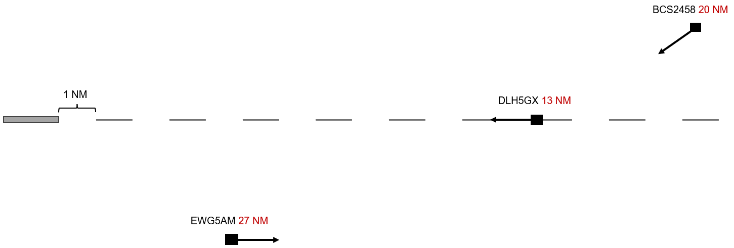
Achieving the desired spacing
To estimate the distance of the aircraft until touchdown, observe a plane that is already on the ILS. Then, you need to determine the spacing you currently need. If, as in the above example, you need a final approach spacing of 7 NM, start with the first aircraft and count backwards in increments of 7. So, if the first aircraft is at 13 NM, the next one, at the same speed, must fly exactly 7 NM more (i.e., 20 NM). The ones behind will need to fly 27, 34, 41 NM, etc.
There are various ways, procedures, and tips to achieve this:
Downwind
The downwind leg runs parallel, in the opposite direction to the final approach, and should be about 5 NM away from it. Many airports already have arrivals or transitions set up like this. The planes should not exceed 220 KIAS to avoid overshooting when turning onto the final approach.
If you turn the following aircraft when the preceding one (already established on the LOC) is abeam, this will result in a spacing of 5.5 to 6 NM between the two aircraft on the ILS (Figure 1), assuming both aircraft have the same speed. This refers to the moment when the aircraft turns, not when you as the controller start speaking – you need to issue the instruction a bit earlier. If you turn the aircraft when it's 0.5 NM past abeam, you will gain an extra NM of spacing because the aircraft must "fly back" that 0.5 NM (Figure 2). Each additional NM of downwind results in 2 NM more flying distance. Turning the aircraft when it's 0.5 NM before abeam will result in 1 NM less spacing. With this rule of thumb, you can calculate any desired spacing. Experiment a little and fine-tune with earlier or later speed reductions.
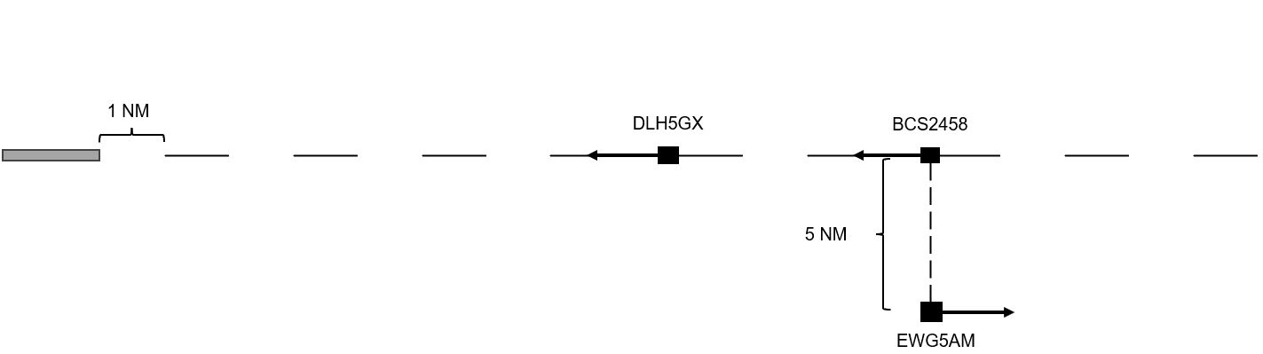
Figure 1
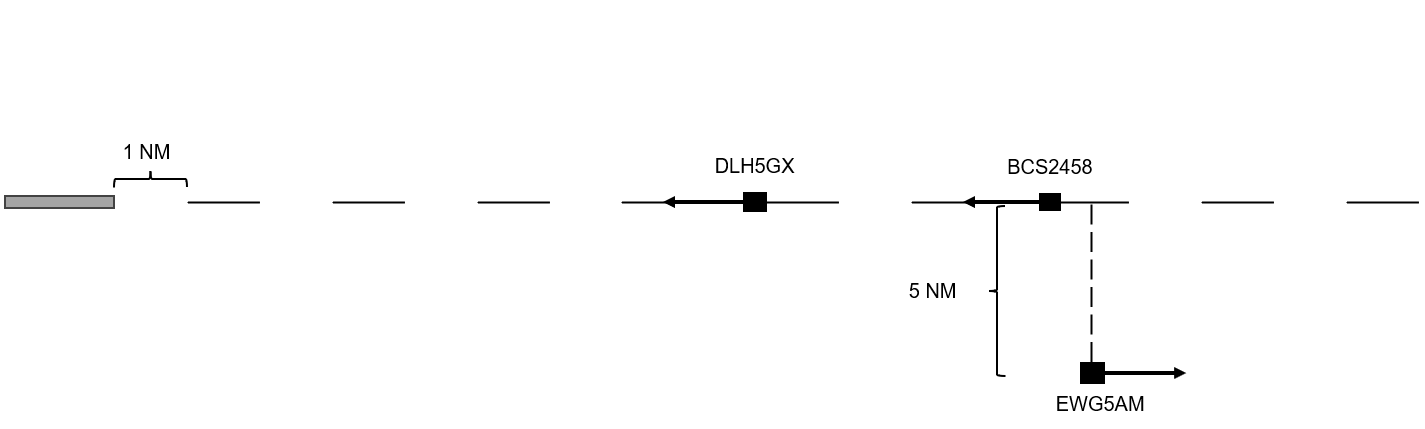
Figure 2
If the aircraft is turned onto the final approach just two radar updates (10 seconds) later than planned, it will have already covered 1 NM in that time. This means it will need to fly 2 NM more, which is rarely corrected with speed adjustments. Over 30 seconds, this results in 6 NM more flying distance and reduces the runway capacity by 50%. This example clearly shows why your priority should always be the final approach!
Base
You can use the base leg depending on local conditions and traffic to turn aircraft from the downwind onto the final approach (Figure 1) or to allow aircraft to fly more or less "directly" onto the final approach (Figure 2).
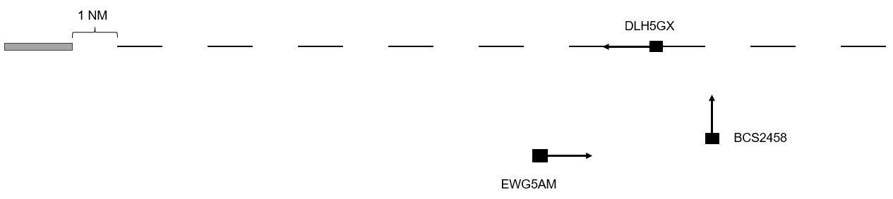
Figure 3
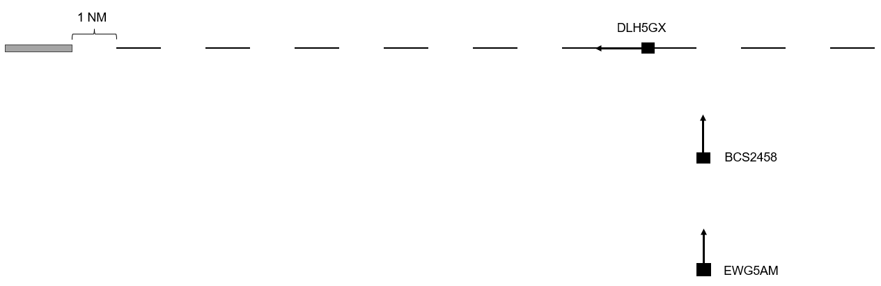
Figure 4
If you look closely at the figures, you'll see that the distance of BCS2458 (and EWG5AM in Figure 2) relative to the final approach remains constant. The only variable distance is that of the Lufthansa moving westward toward the runway. Therefore, the base leg should ideally be at an angle of 90° or more to the final approach in both cases. Otherwise, situations like in Figure 5 can occur. Here, the distance from DLH5GX to the runway decreases, while the distances of BCS2458 and EWG5AM increase. With each radar update, the spacing relative to the approach changes. This makes it much harder to accurately turn the aircraft one after the other onto the final approach.
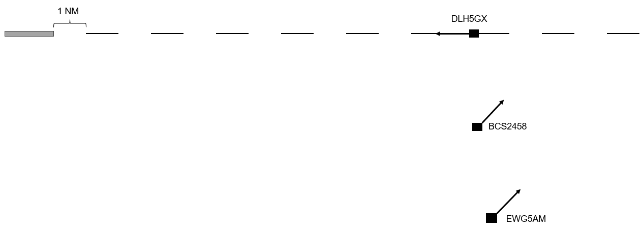
Figure 5
Final Approach
The goal of the approach controller should be to guide all aircraft onto the final approach at more or less the same point. To achieve this, it’s important that the feeder receives neither too few nor too many aircraft. In the first case, the intercept point shifts closer to the airport; in the second case, it shifts farther away.
Of course, you won’t always manage to have every plane intercept at exactly the same point. However, at most German airports, 10-15 NM is a good guideline. Generally, on Vatsim, the goal should be to have as short a final approach as possible, as this minimizes the effects of technical differences, such as wind or speed variations.
Adjustments
Slow aircraft
One of the more challenging situations is when you need to integrate an aircraft into the sequence that will fly the final approach significantly slower than the others. Here, too, you should try to let the plane fly as short a final approach as possible. Over 20 NM, a speed difference of 60 or more knots will waste much more space than over 8-10 NM. Therefore, the aircraft should always be kept near the ~10 NM final, for example, by having it fly circles. When the opportunity arises, you can then slot it in. How many miles do you need to the next aircraft? You can calculate this again using the formula:
Speed difference / 60 = loss of spacing per minute
For example, if the slow type is flying the ILS at 120 KTS and cleared for an 8 NM final, it will take about 4 minutes to reach touchdown. If the following traffic is flying at an average of 180 KTS, it gains 1 NM per minute on the slow type. Therefore, the following plane needs at least 4 NM more than the required separation to avoid catching up to the slow aircraft. In such a scenario, it’s always better to err on the side of caution and give one or two miles more rather than too few.
A further video with an interesting approach can be found here:
https://youtu.be/VNcSB-c6atU?si=Wo2vHTW9Dgm0zHE6
Wind
Wind can also affect the headings used for downwind or base legs. For an east-west runway with a west wind pushing aircraft eastward, a heading of 360° for the base leg may need to be corrected 5 or even 10 degrees to the left. A heading of 180° may need to be corrected to the right. Tools like windy.com, which show the wind at altitude, can help assess the potential effects.
In cases of strong headwind on the final approach, it’s important that aircraft are not turned too early or too late onto the final. As soon as the aircraft turns onto the intercept heading, its ground speed begins to decrease. If the trailing aircraft is turned too early, speed control will be less effective than in calm wind conditions. If the aircraft is turned too late, it becomes much harder to make up the gap with a headwind, and the aircraft will fly more distance in the final turn.
Think about the effects of wind when it’s perpendicular to the approach (e.g., from the north or south on an east-west runway). What difference does it make on the base leg when aircraft from one direction have a tailwind and others a headwind, even if all are flying at 220 kts?
Consider, before logging in, what adjustments might be sensible and observe how it works with the first few aircraft.
Pilots
With some experience, you can usually gauge whether a pilot is new and/or unfamiliar with their aircraft from the first contact. Keep this in mind when planning and issuing instructions.
Give a new pilot an extra mile or two on the final, keep in mind that their instructions may be carried out with some delay, and don’t waste time scolding them for mistakes. Focus instead on resolving the situation.
Not everything is lost because of one pilot!
Holding Management
There can be various reasons why you have to initiate a holding. One reason can be that the arrival controller can simply no longer manage to get the necessary spacing between arrivals rushing in. Holding is then used as a means of creating spacing.
Another possible reason is that the approach controller stops accepting any more aircraft because, for example, the runway is closed.
Initiating a holding pattern
Holding is always managed by the CTR controller. If you know that you have to initiate a holding pattern, you usually slow down all aircraft still flying towards the holding fix to "minimum clean speed" so that they have to spend as little time as possible in holding. This is more economical.
It is important to make sure that all aircraft arrive at the holding fix with a 1000 ft separation, so ideally you would work with rates in descent.
HOLD AT / OVER (significant point, name of facility or fix) MAINTAIN / CLIMB / DESCEND (level) *(additional instructions, if necessary)* EXPECT FURTHER CLEARANCE AT (time) / IN (minutes) / EXPECTED APPROACH TIME (time)
The pilot should always be informed where and how high to fly into the published holding pattern. In addition, an expected approach time (EAT - Expected Approach Time, i.e. time when to leave holding) must be calculated if a stay in the holding patternof more than 20 minutes can be expected and be communicated to the pilot together with the holding instruction. For military aircraft (1-2 seater jets), the EAT must always be added regardless of the 20 minutes, as they generally calculate their fuel very tightly and may have to divert directly to the alternate. In addition, the pilot must always be informed if a new EAT deviates from the previous one by 5 minutes or more.
DLH123, hold over SPESA, maintain FL130, expected approach time 1230.
In addition to the ‘general holding instruction’ shown here, there is also a ‘detailed holding instruction’. This contains the following points:
- holding fix
- holding level
- inbound magnetic track to the holding fix
- direction of turns
- time along outbound leg or distance values, if necessary (up to FL140 1 minute, at or above FL150 1.5 minutes)
- time at which the flight can be continued or a further clearance can be expected
It is standard procedure to give general holding instructions unless one of the following points is met:
-
The pilot follows a holding procedure other than the published one
-
The pilot reports that he does not know the published holding procedure
-
The pilot must enter holding over a point for which no holding procedure is published
The callsign and altitude can be highlighted in color in the tags when using Topsky to make it easier to see the aircraft in holding patterns.
Holding capacity
Incidentally, a holding pattern should not be assigned too high. If so many planes have to hold that the holding stack would be reach above FL200, you have to think about opening a second holding which has to have enough distance from the first one. This is often referred to as "enroute holding". If this is no longer possible in your own sector, the adjacent center sector must open a holding, as no more inbounds can be transferred from them to you.
Terminate holdings
Having the aircraft all circle in the holding pattern does of course not really present a challenge, but it becomes a real art as soon as the approach controller starts receiving airplanes again and you have to hand them over to them with a 10 NM spacing. Handing the whole holding stack over to APP so the controller can take airplanes out of the holding on their own only makes sense if the APP has at least the lowest 3-4 planes on their frequency. This is the only way they can get the airplanes into a sequence without wasting a lot of space. Ideally, CTR manages the exit from the holding pattern and only then hands the aircraft over to APP (coordination may be required for where CTR should clear the planes to).
Letting each aircraft complete its holding and only then continue clearing them to APP definitely is a bad tactic. Doing this makes the 10 NM spacing you are aiming for an absolute coincidence, if it works at all.
To improve this, you have to think ahead a lot: you have to instruct the next aircraft to leave the holding well in advance to stay on the outbound heading, on the "downwind" of the holding pattern, so to speak. Once it is shortly beyond the abeam point to the preceding traffic (which is already flying towards the holding fix, i.e. is virtually in the "final" of the holding), you simply turn it in behind it and you should get pretty much exactly 10 NM out of it. We aim for so much more spacing than when vectoring to the ILS because the aircraft are always significantly higher and therefore have a higher GS (although they are also flying at approx. 220 KIAS). At this point, the corresponding measure for the aircraft following the aircraft that has just turned back to the holding fix also has to have been initiated already. These holding patterns and their management really have a lot to do with advance planning.
It is also very important to always quickly follow up with the cleared levels. As soon as a plane has left the holding, you clear the plane above it down to this now clear level. You can then have it report reaching this level, for example, so that you can immediately move the plane above it and do not forget to keep the cascade of airplanes being cleared down to the cleared levels below them moving.
"Clearing out" a holding is therefore almost the same as feeding to the ILS. There is a downwind and a final, but you also always have to make sure that the airplanes are instructed to hold the outbound heading well in advance, because if you miss it once, you will lose quite a few miles.
Holding Times
Holdings should only be used for as long as necessary to avoid arrival running empty. APP and CTR must coordinate how long the aircraft need to be delayed. Often just one lap in the holding pattern (about 4 to 5 minutes) is enough to make sure that enough capacity is available again.
It helps to consider or measure when the last aircraft is on final at APP. Taking into account the remaining distance for the inbounds, the reduction of the holding can be planned.
Further links
- Skybrary: Holding Pattern
Low Visibility Operations (LVO) - Arrival
In case of low visibility conditions, the controller has to adapt the procedures at the airport to ensure a safe continuation of flight operations.
However, controllers do not differentiate between CAT II and CAT III operations. The pilots must decide for themselves which approach they can fly based on the prevailing RVR and ceiling.
Low visibility operations become active when the runway visual range (RVR) is equal or less than 600 m and/or when the ceiling (BKN / OVC) is below 200 ft or when there is no vertical visibility.
The separation between two approaching aircraft or one approaching and one departing aircraft must be increased compared to standard operations so the ILS signals are not disturbed by approaching and departing traffic or by taxiing aircraft or vehicles on the ground.
Approaches must be given the prevailing RVR together with the approach clearance. Which ILS category is used is up to the pilot and is therefore not mentioned in the clearance.
DLH123, turn left heading 220, cleared ILS runway 25L, RVR 300 metres.
Depending on the volume of traffic, it may be necessary to increase the spacing between approaches to avoid missed approaches.