Practical Procedures
- Delivery / Ground / Tower
- Pushback and Taxi
- Priorities - Ground & Tower
- Tower Efficiency
- Not withholding a takeoff or landing clearance
- Conditional Lineup
- Tower Separation
- Missed Approach - Controller Guide
- Deicing using the example of EDDM
- Low Visibility Operations (LVO)
- Approach
- Radar Vectors
- Speeds
- Establishing approach sequences
- Holding Management
- Low Visibility Operations (LVO) - Arrival
- Center
- Runway Change Guide
- Emergencies - Controller Guide
- Identification
Delivery / Ground / Tower
Pushback and Taxi
Ground/Apron is responsible for pushback and all taxi guidance at the airport. Ground and Apron differ in that in reality ground is managed by DFS and apron is staffed by the airport operator itself. In Germany, there are six airports with an apron station: Berlin, Dresden, Erfurt, Frankfurt, Hamburg and Munich. The respective areas of responsibility are regulated in these airports’ SOPs.
Taxi guidance on the ground should not be underestimated, as it requires a great deal of attention and foresight, depending on the airport!
Pushback
As aircraft cannot taxi backwards, they usually have to be pushed back from the parking position onto a taxiway by a tug (tow truck). In some cases, there are also parking positions where the pilot can taxi out under his own power (taxi out positions). Details on that may be outlined in the airport's SOPs.
As a rule, the pushback pushes onto a taxiway. If there are several options for the pushback, the controller must inform the pilot which option will be performed. Most frequently, the taxi clearance specifies the direction the aircraft should face after the pushback (e.g. “facing west”). Differing taxiways can also be specified (e.g. a taxiway that is not directly behind the gate or, if available, a blue/orange line). The controller should already have a plan for the subsequent taxi guidance before the pushback in order to work as efficiently as possible.
| Station | Phraseology |
| Pilot | München Apron good day, DLH5KC, stand 205A, request pushback. |
| ATC | DLH5KC, München Apron good day, pushback approved, facing south. |
| Pilot | Pushback approved, facing south, DLH5KC. |
Please note that a taxiway will be blocked by a pushback for several minutes (varying depending on aircraft type and pilot). For this reason, it is particularly important to keep an eye on the entire taxiway and to work proactively, especially at large airports.
If the pushback is not possible immediately (e.g. because there is already an aircraft behind it or an inbound has to be waited for), the pilot must be informed of this with a “hold position” and, ideally, a brief information on what he still has to wait for. If there are two waiting outbounds on the frequency that are both ready for the pushback, it may also be advantageous to deviate from the "first come, first serve" principle, depending on the situation, if this can reduce the overall waiting times.
Taxi
After the pushback has been completed and the pilot reports that he is ready to taxi, he is usually guided to the holding point of the departure runway or, at some airports, up to the transfer boundary between the areas of responsibility of tower/ground and apron. As a rule, the pilot may not deviate from the yellow taxi guidelines. Exceptions, if any, are regulated in the respective SOP.
The pilot may also be given taxi clearance if there is another aircraft in front of him which is not yet ready to taxi. The pilot must stop behind it and will only continue taxiing as soon as the aircraft in front moves. With very complex taxi guidance, it is helpful to divide the route into several sections in order to simplify and accelerate the pilot's readback and minimize the risk of errors.
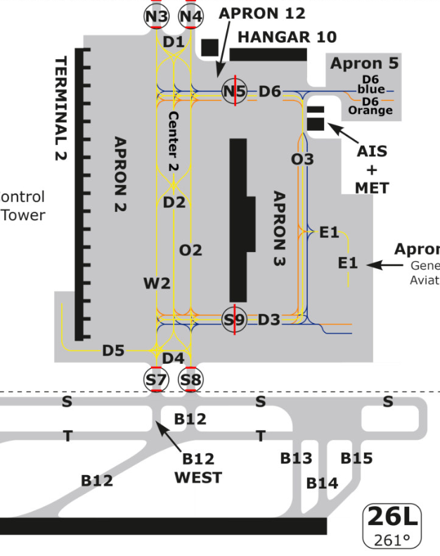
Groundlayout München EDDM
Depending on the traffic situation, hold shorts or give way instructions (see below) must be used to resolve possible conflicts on the ground. If it can be assumed that two aircraft are not in conflict with each other despite crossing taxiways (e.g. due to sufficient distance), no such instruction needs to be given. However, the situation must be monitored continuously and action needs to be taken if necessary.
The same applies to inbounds. They are handed over from the tower to ground/apron in time before the handover limit and then receive their taxi instruction to the planned parking position.
| Station | Phraseologie |
| Pilot | DLH5KC, request taxi. |
| ATC | DLH5KC, taxi to entry S8 via W2 D2 O2. |
| Pilot | Taxi to entry S8 via W2 D2 O2, DLH5KC. |
-
Note on taxi clearance: By definition, the phrase TAXI never exists without a following VIA or TO.
-
TAXI VIA means "taxi along the taxiways/points....". A taxi instruction must also ALWAYS contain a clearance limit. If you start your instruction with TAXI VIA, there must always be a HOLD SHORT in the same instruction that describes up to which point the clearance extends (clearance limit).
-
TAXI TO means "taxi to...." and thus describes the clearance limit up to which the pilot may taxi. If you start your instruction with TAXI TO, there must always be a VIA in the same instruction describing the route to the pilot.
Keeping traffic moving on the ground
-
-
It sounds trivial, but it is very efficient. Once the aircraft are moving, they will be out of your area of responsibility faster than if they are stationary. For every aircraft that has to stop, additional time passes, it has to be called again to continue taxiing and can sometimes be forgotten. If there is a lot of traffic, the frequency can quickly become full. Instead, whenever possible, use “give way”-instructions or adapt the routing on the ground.
As an ATCO controlling a ground station, you should regularly scan your ground layout: Is a plane about to stop unnecessarily? This should be avoided.
Hold Short
Hold short calls are used to stop rolling traffic before a certain taxiway. It should be noted that further taxi guidance is canceled after the hold short. If the aircraft is to continue taxiing, it must be informed (again) of the complete further route. If it is probable that the aircraft will have to wait at a certain point, it should only be given the necessary taxi routes to get to this point.
| ATC | TUI4PH taxi to holding point runway 18 via L N1 N, hold short of N5. |
| ATC | TUI4PH continue taxi via N. |
| ATC | RYR1ME taxi to holding point runway 24 via B A A3, hold short of runway 14L. |
If you want a sequence of taxiing aircraft to stop at a certain point, it is sufficient to give the first aircraft the hold short. All subsequent aircraft will inevitably have to stop behind it. However, it is important to note that as soon as the first aircraft rolls again, the entire sequence will start moving again.
If the route to the active runway leads across another runway (e.g. in Cologne and Hamburg), explicit clearance is always required to cross this runway. If the runway is outside your own area of responsibility, a hold short must be instructed.
Give Way
Another way to resolve potential conflicts on the ground is to use the give way instruction. Here, the pilot is given the task of giving right of way to other taxiing traffic. It is important to tell the pilot where he has to let the other aircraft pass (‘at D3’), what other traffic he has to watch out for (company / Lufthansa A320) and where the traffic is coming from. To avoid misunderstandings, only the direction from which the other traffic is coming should be indicated, not where it is taxiing to.
| ATC | DLH5KC give way to company A320 crossing right to left on D3. |
-
Use ground status and label hold shorts
-
Ground status labels are very helpful for keeping an overview yourself, but also to give other controllers the opportunity to quickly get a situation on the ground. They should especially be used when there is a lot of traffic and many controllers simultaneously work at the airfield with different lists.
In this context, it is also advisable to label given hold shorts as tower or ground when there is a lot of traffic. This reduces the risk of forgetting the aircraft in front of an intersection, as the hold short appears quite prominently in the third line of the label.
Intersection Departure
On Vatsim, traffic is usually distributed by ground or apron to the various intersections (taxiway junctions) of the runways. Ideally, the pilot reports which intersection he can take off from when he is ready to taxi or during the initial call for further taxiing.
| Pilot | München Ground hallo, DLH5KC Entry S8, able B12. |
| ATC | DLH5KC, hallo, taxi to holding point runway 26L, intersecton B12, via B12. |
| ATC | DLH5KC, hallo (no benefit), taxi to holding point runway 26L via S and B13. |
If it benefits the tower’s departure sequence or the pilot (e.g. time saving), an intersection departure can be assigned. However, there is no obligation to do so, so the pilot can also continue to the beginning of the runway as normal. It is always safer for a pilot if they have more runway available. If they have to wait longer for take-off due to landing traffic, wake turbulence or generally due to the take-off sequence, this time should also be used to taxi on to the start of the runway.
If the use of an intersection is not part of the published standard procedures of an airport (AIP), the pilot must always be asked beforehand whether he can use the intersection. Details can be found in the respective SOP of the airport.
| ATC | DLH5KC, advise able to depart from runway 26L, intersection B10. |
As a ground/apron controller, you should also always take care not to block your main taxiways by assigning the same intersection if you do not know the departure sequence of the tower (e.g. taxiway L in Frankfurt). If in doubt, you should coordinate with the tower or give a handoff as early as possible so that the tower can take the aircraft into the intersection itself if necessary.
Changed taxi guidance
The traffic situation on the ground is constantly changing, especially at large airports. For this reason, a potential conflict on the route given to the pilot can arise while they taxi or longer waiting times may become necessary, for example due to a pushback. In this case, the controller can change the route of the aircraft on the ground in addition to the already known instructions.
| ATC | DLH5KC revision, continue via W2, hold short of D4. |
Handover of aircraft
When does the handover of an aircraft between two ground stations actually take place?
In short: hand over your aircraft when you no longer need them. More precisely: Pilots should be handed over to the next position once:
-
...they have clearance up to the handover point to the next station (in Nuremberg up to the holding point, in Munich on Apron up to entry)
-
...they are conflict-free (i.e. there are no unresolved intersections with other aircraft)
-
...you do not have to give them any further instructions
If all three points are fulfilled, it’s time for: Contact XYZ Ground/Apron/Tower on 1xx.xxx.
In any case, unnecessary stops for the aircraft should be avoided because of you forgetting to hand them over to the tower, for example. Here too, the airport should be scanned regularly to see if any aircraft can be handed over.
Advanced Taxiing
Especially when there is a lot of traffic on the ground, it is important to work efficiently and keep the frequency load as low as possible. It is important to maintain the flow of traffic, reduce unnecessary waiting times and radio messages (few hold shorts, short and concise instructions, early handoffs) and still ensure safety. Here are a few tips that can make your work easier.
NOTE: Only use these procedures if you feel comfortable with them and can handle them! It is also always possible that a pilot may not understand your instructions exactly and will not ask you.
Push and Pull
It doesn't always have to be the classic push back, especially pilots with X-Plane are easily able to pull forward and disconnect the tug at a certain point. This is useful, for example, when two aircraft are pushing next to each other or you want to clear the taxiway for another aircraft in a timely manner.
| ATC | DLH123, pushback approved, then pull foreward, disconnect (tug) short of D2 / abeam stand 217. |
Conditional Pushback
Just like Give Way instructions, conditional pushbacks can transfer responsibility to the pilot. This is particularly useful if an outbound pilot has to wait for another aircraft that must first pass behind him. It is always important to ensure that the instruction is unambiguous and cannot be misinterpreted.
| ATC | DLH123, when clear of outbound company A320 behind, pushback approved. |
| ATC | DLH123, when space permits, pushback approved. |
| ATC | DLH123, when clear of the inbound British Airways A319 for V117, pushback approved, orange line, facing west. |
Intersections First
Aircraft leaving or crossing a runway should be prioritized if possible. This way, tower can allow aircraft to cross the runway more efficiently and with less waiting time for outbounds.
| ATC | DLH123 give way to the vacating Condor A320 from runway 25C. |
| Pilot | Giving way to the vacating traffic, DLH123. |
| ATC | CFG789 number one, taxi right via L, hold short of N8. |
Give Directions
If you need to move quickly or if the pilot is not familiar with the airport, it is always helpful to tell the pilot whether he should turn left or right onto a taxiway (left, right, straight ahead).
| ATC | DLH123, taxi right on L, hold short N8. |
Backtrack
The term "backtrack" (German: Zurückrollen) refers to a procedure in which an aircraft enters a runway from an intersection and then moves in the opposite direction of the runway, proceeding along the runway to the beginning. There, the aircraft turns around so that it can take off from the full runway length. This procedure is particularly used when there is no designated taxiway leading to the runway beginning, or when the taxiway is not approved for certain aircraft types.
It is important to note that during this time, the runway cannot be used for other flight operations (takeoffs/landings). Therefore, the next approaching aircraft should be considerably farther away than during a "normal" lineup, depending on how long the backtrack procedure takes. Details regarding this can be found in the SOPs of the respective airports.
| Backtrack | |
| DLH5EJ, backtrack approved, line up runway 03 | DEEZU, Zurückrollen genehmigt, rollen Sie zum Abflugpunkt Piste 03 |
Priorities - Ground & Tower
In order to ensure safe and smooth flight operations, it is important to work efficiently and safely. It is important to always work proactively and not fall behind the traffic. This includes looking beyond your own area to see what your colleague in the neighboring position is doing, for example.
Setting the right priorities is therefore essential for the safe and efficient handling of air traffic. This helps the controller to focus and maintain control of the airport. The following priorities should be used as a guide:
-
Emergencies
-
Flying traffic (take-off and landing clearances)
-
Runway Clearances (line-ups / unway crossings)
-
Taxiing traffic (avoid stopping anywhere unnecessarily)
-
Pushbacks
-
Startup/Enroute clearances
-
Miscellaneous
In short, remember: "Flying before taxiing before standing".
Priorities are particularly important for time-critical instructions where a few seconds can be crucial (e.g. landing clearance on short final). These priorities also help to ensure your own efficiency, a good use of the airport’s capacity and to avoid frequencies that are too full.
Giving and labeling standbys
When there is a lot of traffic, for the reasons mentioned above, it is no shame at all if the less important things such as enroute clearances are put on standby for a few minutes. In cases like this, you can say something like "DLH123, standby, number 2 for clearance" to the pilot. A standby can also be useful for other reasons, e.g. because the pushback cannot yet be given due to other traffic: "DLH123, standby for pushback due to traffic".
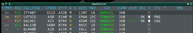
To keep an overview of which aircraft have been given a standby, you can use the request column in the startup or departure list, at least for the outbounds, to highlight standbys so that you don't have to remember them. If, for example, a plane calls in for pushback or enroute clearance and this cannot yet be given for whatever reason, you go to the corresponding line, click on the REQ column and then go to the fitting clearance. You will then see "R1P" in yellow, for example. The "R" stands for request, the number for the number of the aircraft's turn (e.g. 2 if another aircraft before it has the same standby) and the "P" for the type of request (C = clearance, P = pushback, T = taxi, etc.).
Optionally, you can also show the timer column by right-clicking on the "O" in the top left of the list and then activating "Timer". You can then see how long a plane has been waiting.
Finally, you should get into the habit of checking the REQ column regularly so you never forget standbys again.
Tower Efficiency
-
Optimizing the departure sequence
-
A crucial point where many valuable seconds may be wasted, is the take-off sequence. Especially when there are a lot of traffic and narrow gaps, it is important to get the traffic into the air as quickly as possible.
Try to get as close as possible to the minimum separation between departing aircraft to avoid creating unnecessarily large gaps. If you wait just one minute too long, for example, you have reduced the airport’s departure capacity of up to 50%. In order to enable efficient spacing, it may also be necessary to adjust the departure sequence so aircraft do not take off in the order in which they called the tower. At many airports, various intersections can be used for this purpose. Gaps on the frequency can be used for conditional line-up clearances.
It may make sense to deviate from the "first come, first served" principle for the following reasons:
Wake turbulence separation
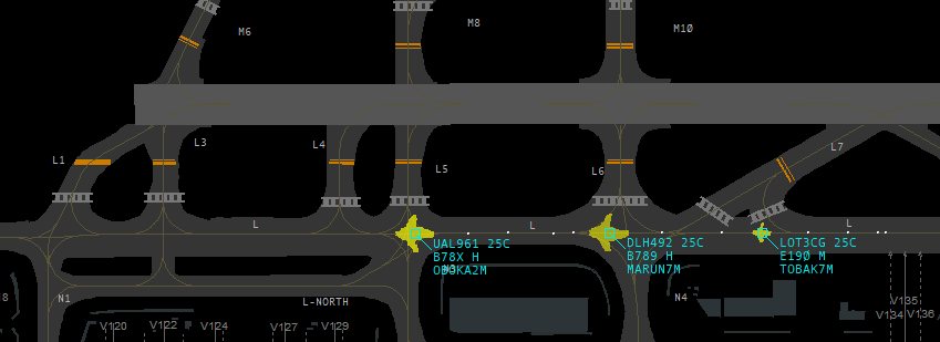
In the picture we have the following constellation: A heavy is taxiing to the runway at the front, followed by another heavy and a medium at the end. If the planes now take off in this order, you need 4 NM between the first two heavies and 5 NM between the second heavy and the medium. This makes a total of 9 NM.
However, if we now prefer the medium and let it take off from intersection L4 as number 1, for example, we only need 3 NM between the medium and the first heavy and 4 NM between the two heavies again. This makes a total of 7 NM. This means we have saved 2 NM directly - that's just under a minute.
Conclusion: If the medium and heavy arrive at the runway at relatively the same time, you should try to give preference to the medium in order to generate the lowest average delay. You should act sensibly though and not let a heavy wait for several minutes just to get a few mediums out first.
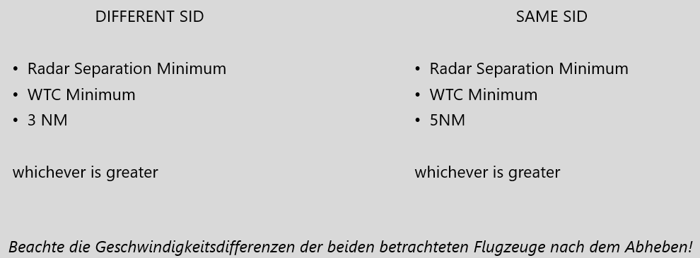
Mixing different SIDs
As you learned in the tower separation article, you usually need 5 NM of separation between aircraft on the same SIDs. With different SIDs, 3 NM radar separation is sufficient.
Suppose you have a situation in which, for example, two aircraft with the same SID are taxiing north to the runway and behind them an aircraft with a different SID is taxiing south to the runway. If you now give takeoff in this order, you need 5 NM between the same SID departures and 3 NM between the north and south SIDs.This means a total distance of 8 NM. However, if you now place the aircraft with the south SID between the two north SID departures, you only have to wait 3 NM in each case, which results in a total distance of 6 NM. This means that one aircraft has to wait a little longer, but another can get out much faster and you have saved an average of 2 NM and therefore also time.
Big performance differences
Assuming you have a C172 IFR waiting at an intersection and a Boeing 777 at the beginning of the runway. You learned above that you should try to avoid wake turbulence. So do you now pull the C172 in front of the B777? If you did this, the B777 could of course take off 3 NM behind the C172, as we only need the radar separation. But in this case, the performance differences are so great that the B777 will have caught up with the C172 within a few seconds, both in terms of speed and altitude. This means that, despite the initial separation, the aircraft quickly will produce a loss of separation. In such a constellation, depending on when the flight paths of the C172 and B777 separate, it might take several minutes until the C172 has left the area the B777 will initially climb into or is 3 NM away from the SID of the B777, ensuring separation.
In such a case, it makes more sense to let the B777 take off first and have the C172 follow with 6 NM wake turbulence separation.
The constellation of the aircraft strongly influences when the performance differences outweigh the wake turbulence separation. In general, it can be said that all jet airliners have a similar performance, at least in terms of speed in climb, whereas props are often significantly slower. However, this does not always apply. If in doubt, it is better to wait a little too long than too short.
-
Avoid missed approaches
-
If there is a risk of loss of separation, the controller must take action. In addition to the option of a go around, the possible alternatives should also be considered. At international airports (EDDx), for example, speed instructions can be given to avoid loss of separation.
However, if there is another aircraft behind the approach controller, this must be coordinated in advance. Reduced runway separation can also be used in appropriate conditions.
Handling close situations
A few questions that most tower controllers have certainly asked themselves at some point, including some food for thought (using the example of a 4 km long runway):
When is the last moment I can clear an aircraft for takeoff while an inbound is approaching?
Let’s assume that the departing aircraft is already on the runway. A statement in the form of "the takeoff clearance must be given at X NM final at the latest" is difficult, because it essentially depends on two factors:
- The speed of the inbound in the last part of the final approach (a slow aircraft still takes considerably longer to cross the runway threshold in the 3 NM final than a fast aircraft)
- The inertia and speed of the outbound (it will take Boeing 747 a few seconds longer from take-off clearance until it actually starts rolling than a CRJ9, for example)
As a rule of thumb, most airliners need approx. 1:05 - 1:15 minutes from the start of the take-off run to flying over the end of the runway on a 4 km long runway. This means that the inbound aircraft should take a little more than 1 minute until crossing the runway threshold to ensure normal runway separation. Reduced runway separation (2,400 m), as may be used in good weather and with appropriate markings, is usually achieved after approx. 45 seconds.
If you now take into account the time between issuing the takeoff clearance and the start of the takeoff run (approx. 3 - 10 seconds), this means that the takeoff clearance for normal runway separation should be given when the inbound still needs a little more than a minute to reach the runway threshold (based on a 4 km runway; for a 3 km runway, you can deduct another approx. 10 seconds). For reduced runway separation (2,400m), it is also sufficient if the inbound will take just under a minute - but this will produce a close spacing, as in the picture below, and it is all the more important to make sure that the outbound actually rolls off.
But how do I know how long the inbound needs from its current position to the runway threshold? There are two possibilities:
- Calculate: An inbound flying exactly 120 knots GS flies 120 NM / hour, i.e. 2 NM per minute. In other words, it still needs one minute in the 2 NM final. An inbound that flies 150 knots GS flies 150 NM / hour, i.e. 2.5 NM per minute. In other words, he still needs one minute in the 2.5 NM final. Everything in between must then be roughly interpolated in your head based on these calculations
- Set the speed vector to one minute (in Euroscope via the top toolbar): When the minute vector meets the runway threshold, it will be exactly one minute until the inbound crosses it. The take-off run should have already been started a few seconds earlier for normal runway separation; otherwise you will "only" achieve reduced runway separation.
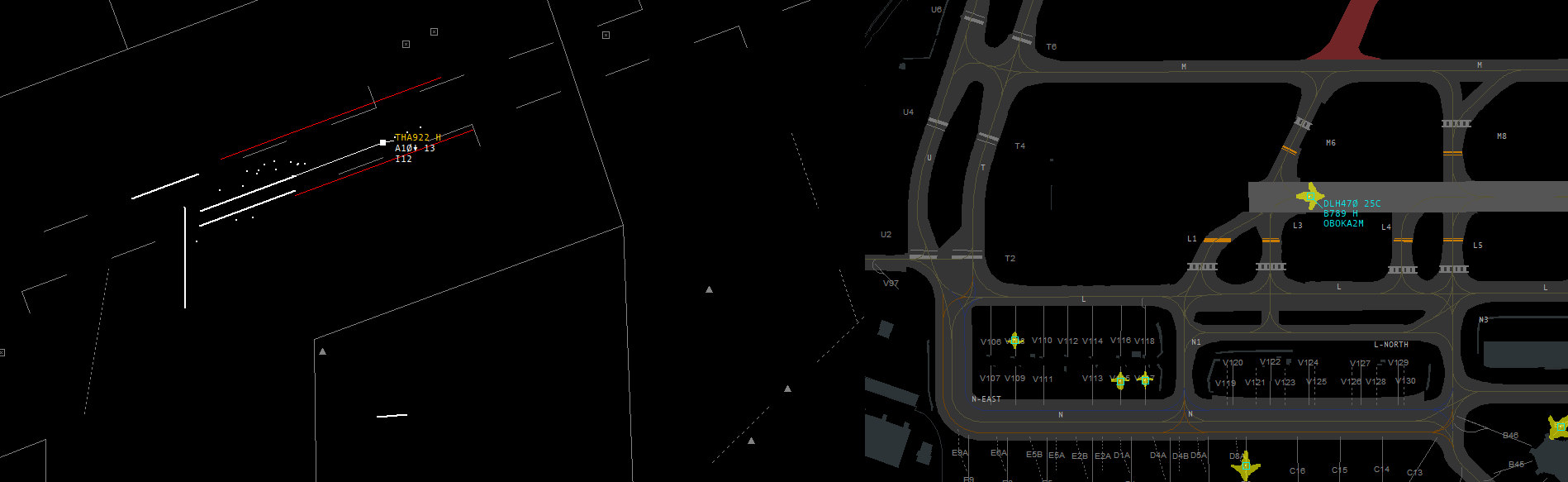 According to the speed vector, THA922 still needs 1 minute to reach the runway threshold, i.e. DLH470 must begin its take-off run in the next few seconds so we can maintain reduced runway separation. Normal runway separation is no longer possible, however, as the Thai would still have to be more than 1 minute away.
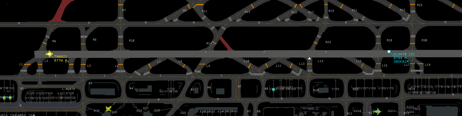 Result: With a buffer of a few hundred meters, we have reduced runway separation (the 2,400m marker is at L14)
What if the plane is still at the holding point?
The time for the lineup must be added to the minimum times mentioned above. This depends very much on the type of intersection (90-degree intersection vs. high-speed turnoff intersection like in EDDM) and also on the type of aircraft. A B748 lines up way more slowly than a small A320. Take a look at the typical lineup times for your airport. In the worst case (sluggish aircraft, 90-degree intersection) this can take around 60 seconds, in the best case (agile aircraft, angled intersection) sporty pilots are in the line-up position after just 20 seconds. The average is somewhere in between. As a result, you can average that if the inbound is still about 2 minutes away from the runway threshold, you can give line-up and takeoff clearance from the holding point if you motivate the pilot accordingly (see below) and usually get normal runway separation. Here, too, you can either calculate or display the 2-minute speed vector to know where the inbound will be 2 minutes out.
How much separation do I need between two inbounds to get an outbound between them?
In addition to all the factors mentioned above, there is another factor to consider: the availability and type of runway exits. In such a constellation, the factor limiting the outbound takeoff clearance is usually that the first inbound has to get off the runway first. At airports such as Munich or Frankfurt with many available high-speed turnoffs, under good conditions the time between flying over the runway threshold and leaving the runway is around 45 seconds. Heavy aircraft need slightly longer than 60 seconds. On Vatsim, there is also the factor of pilot quality - if you cannot assess the pilot exactly, you should calculate rather conservatively and assume a runway occupancy time of 1 - 1.5 minutes.
During this time, the outbound pilot will usually already have completed the lineup and can be cleared for take-off. The same rough values apply as explained above.
If you now add the two values - runway occupancy time of the first inbound + time from takeoff to flying over the runway threshold of the outbound, you arrive at around 2 minutes (ambitious) to 2.5 minutes (conservative). This means that the second inbound should still be 2 - 2.5 minutes away from the runway threshold when the front inbound is over the runway threshold. Depending on the wind and aircraft type, this means a gap of around 5 - 6 NM at touchdown. Most airport SOPs will therefore recommend take-offs and landings on the same runway to create 6-mile gaps between the inbounds to get outbound between. Now you also know the theoretical background to this.
How can I increase my chances on the frequency that a close situation works out?
Luckily, there are a couple of phraseology tools which you may and should use for closer situations:
An inbound shall vacate the runway quickly?
"DLH4JA, after landing expedite vacating, wind 280 degres, 5 knots, runway 25C cleared to land"
An outbound shall be prepared to depart quickly?
"DLH3CN, prepare for immediate departure (as soon as runway is clear)"
Thereafter:
"DLH3CN, wind 280 degrees 5 knots, runway 25C, cleared for immediate takeoff"
There will be an outbound just before the inbound touches?
"CFG4MA, reduce to final approach speed, expect late clearance, traffic, A320 departing ahead"
- "Reduce to final approach speed" may only be used when there is no traffic behind which would affect separation. Otherwise, this has to be coordinated with the approach controller
- Giving the traffic information is beneficial because in case of Reduced Runway Separation, you have already given the traffic information before
- "Expect late clearance" makes sure that the pilot does not unnecessarily ask for the landing clearances e.g. on 2 NM final
Not withholding a takeoff or landing clearance
This procedure is not a mandatory part of S1 training.
Introduction
Under certain circumstances, a take-off or landing clearance can be issued even if the runway is not clear yet. However, there must be reasonable assurance that the runway will be clear as soon as the inbound aircraft crosses the runway threshold or the outbound aircraft begins its take-off run.
This procedure can reduce the frequency load and increase efficiency on the frequency, especially when traffic volumes are high. However, applying it appropriately requires a high level of knowledge and experience.
The crux of the matter is the requirement of "reasonable assurance" for a clear runway as soon as the take-off or landing clearance takes effect. Of course the term "reasonable assurance" allows for a wide variety for interpretation. Because flight safety is nevertheless the top priority in all procedures, it is advisable to delete the word "reasonable" from your own mindset if possible and only apply the procedure if there is "assurance" that the relevant conditions will be met at the necessary time.
Takeoff clearance
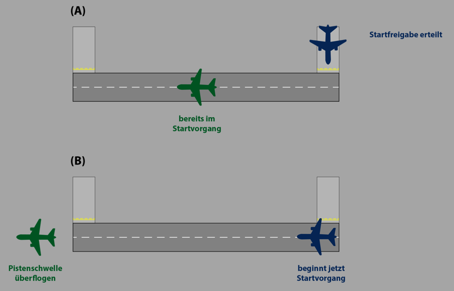
Situation (A): Without the procedure described in this article, I may not issue a take-off clearance at this time, as GREEN has not yet crossed the runway end and the runway is therefore still occupied. But considering "reasonable assurance", a controller can issue the take-off clearance at the time of situation A if they have "reasonable assurance" that GREEN will have already flown over the end of the runway and the runway will be clear when BLUE begins the take-off run. This situation is illustrated in situation (B).
This procedure can also be used under reduced runway separation (RRS). Wake turbulence and/or radar separation must still be ensured if necessary.
Landing clearance
Situation (A): Without the procedure described in this article, a landing clearance would not be possible as the runway is still blocked by the landing aircraft GREEN. As controller, however, I can clear the landing by "not holding back a landing clearance" if I have "reasonable assurance" that GREEN will already have left the runway and the runway will therefore be clear when BLUE crosses the runway threshold. In situation (B), the above has occurred and the procedure has been applied correctly. However, for the reasons mentioned under "Take-off clearance", it is difficult to predict the speed when an aircraft leaves the runway and thus to achieve "reasonable assurance".

The procedure can also be used if a departure takes place before the landing traffic. Once this has taken off, it is relatively easy to predict with "reasonable assurance" whether the runway will be clear when the approach crosses the runway threshold. In this case, the landing clearance may be given before the departure has flown over the runway end, provided that the runway will be clear when the approach flies over the runway threshold.
This procedure can also be used under reduced runway separation (RRS). Wake turbulence and/or radar separation must still be ensured if necessary.
Phraseology
The phraseology does not change compared to the "normal" take-off and landing clearances. Traffic information is not mandatory when using this procedure. However, as always, traffic information can contribute to better situational awareness on the part of pilots and controllers.
Examples
The main purpose of this procedure is to use the frequency more efficiently, especially when there is a lot of traffic, by for example avoiding a second unnecessary radio call.
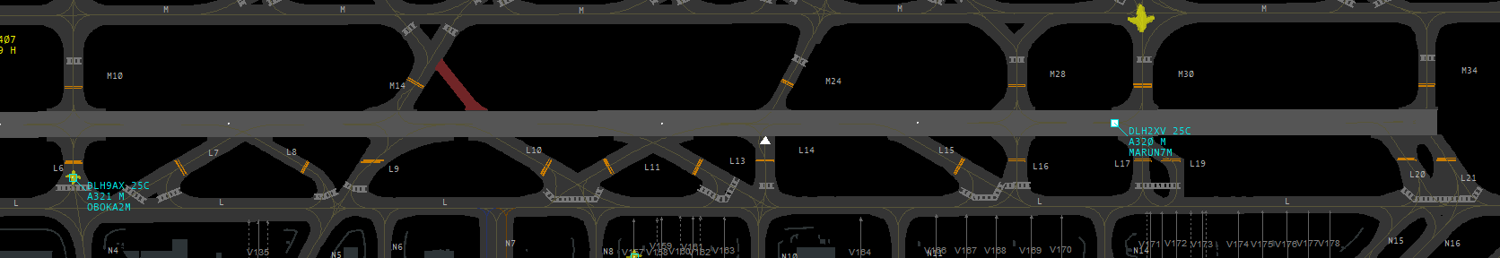
Example 1 (see picture): DLH9AX is at the holding point and reports ready. The previous departure is airborne and will have flown over the end of the runway in approx. 10 seconds. Thanks to this procedure, I can give the takeoff clearance directly, even though there is no runway separation at this point. I have reasonable assurance that the runway separation will exist at the time when the following aircraft begins its takeoff run, as certainly there will be more than 10 seconds between the lineup instruction and the start of the takeoff run.
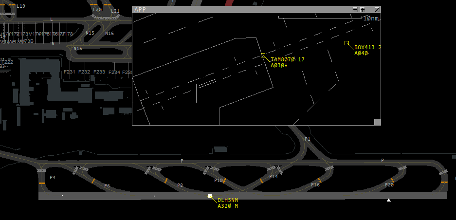
Example 2 (see picture): TAM8070 reports on 8 NM final approach. The previous inbound has landed and is slowing down on the runway. Thanks to this procedure, I can give the inbound caller their landing clearance directly with the initial call, even though there is no runway separation at that time. I have reasonable assurance that the runway separation will exist at the time when the following inbound flies over the runway threshold, as it still needs approx. 3 minutes to reach the runway and the leading inbound is about to leave the runway.
Of course, as the controller I still have to monitor the situation and if for any reason the separation is not given, I have to withdraw the clearance.
The procedure should not be used in close situations (e.g. if the following inbound is already on short final and the leading inbound has not yet completely left the runway). In this case there is no reasonable assurance about the separation at the time of the threshold overflight. Instead, you should delay the landing clearance until the runway has actually been cleared.
Conditional Lineup
Introduction
At all controller stations, it is extremely important to use the frequency as efficiently as possible. In our heads, we may be able to think about and work on two things at the same time, but on frequency, we cannot give two instructions to different aircraft at the same time. This makes it advisable to prioritize transmissions in order to have time for other transmissions later. An ideal option for this is the conditional lineup clearance. It allows you to delegate the clearance to the pilot and instruct him to taxi onto the runway after a certain amount of traffic.
It is important to always tell the pilot exactly which traffic is involved! There must also be good visibility so that the pilot can see the other aircraft. If the weather conditions are poor or the angle of the intersection is unfavorable (more acute than 90°), the pilot must first be asked whether he can see the traffic in question.
As mentioned above, this procedure is intended to make better use of gaps in the frequency and thus increase efficiency. It should be noted that a conditional clearance is significantly longer and takes more time than a standard one. Depending on the traffic situation, a conditional clearance can be significantly more efficient than a normal lineup. If, for example, one can expect that by the end of the call the landing traffic has already flown over the runway threshold or someone else has already started the take-off run, a normal lineup is probably more suitable
For departures
When traffic volumes are high, it can be very important on some airports to achieve efficient spacing of departures and not lose any time. To make this possible, the outbounds should start their lineups as soon as possible. Here, the controller can work well in advance and guide the aircraft onto the runway according to their planned departure sequence.
Several conditional clearances at the same time are only possible if the restricting aircraft is the closest aircraft to the restricted aircraft. This is explained further in the example below.
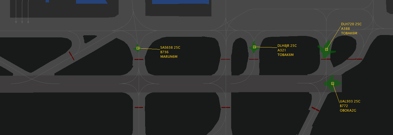
Example for a conditional lineup in Frankfurt runway 25C (click for full screen)
| Station | Phraseologie |
| ATC | DLH720, after departing Boeing 777, lineup runway 25C behind, number 3 for departure. |
| Pilot | After departing Boeing 777, lining up runway 25C behind, number 3, DLH720. |
| ATC | SAS638, after next departing Boeing 777 full length, lineup runway 25C behind. |
| Pilot | After departing Boeing 777 full length, lineup runway 25C behind, SAS638. |
The words “after" must be mentioned at the beginning and the word "behind" at the end, this needs to be read back by the pilot! If the pilot is not next in the departure sequence and has received a conditional clearance, he should be informed of this position in the sequence (e.g. number 3 for departure) to avoid misunderstandings.
The airline should not be explicitly mentioned in the description of a restricting aircraft. Due to various leasing agreements and other commercial contracts, Lufthansa flights, for example, are often operated by Air Dolomiti aircraft. In this case, mentioning "Lufthansa" would confuse the pilots, as the relevant aircraft actually sports an Air Dolomiti livery. Instead, the description should be based on the aircraft type and position.
The following instruction would not be possible:
| ATC | DLH8JR, behind departing company Airbus A380 via L3, lineup runway 25C and wait behind, number 4. |
Simultaneous conditional clearances are only possible if the restricting aircraft is the next aircraft taxiing past the restricted aircraft. In this case, the restricting aircraft for the DLH8JR would be the DLH720. However, DLH720 is not the first aircraft to roll past DLH8JR, as UAL933 starts its take-off run first and thus rolls past DLH8JR. The conditions are therefore not met.
For approaches
In order to use the gap between two approaches for a departure (see also Tower efficiency), the lineup needs to take place as soon as possible after the first landing aircraft has crossed the runway threshold. This allows the take-off clearance and take-off run to take place as soon as the landing aircraft has left the runway.
| Station | Phraseologie |
| ATC | DLH5KC, behind next landing A320 on 2 NM final, lineup runway 26L behind. |
| Pilot | Behind next A320, lining up runway 26L behind. |
As stated before, the airline should not be explicitly mentioned in the description of the aircraft. Due to various leasing agreements and other commercial contracts, Lufthansa flights, for example, are often operated by Air Dolomiti aircraft. In this case, mentioning "Lufthansa" would confuse the pilots, as the relevant aircraft actually sports an Air Dolomiti livery.
The same rule stated above also applies here: Several simultaneous conditional clearances are only possible if the restricting aircraft is the next aircraft taxiing past the restricted aircraft. For example, a conditional lineup behind a landing aircraft may not be issued if an aircraft will still taxi past the waiting aircraft during the take-off run before the restricting landing aircraft.
Tower Separation
General
All control towers operated by DFS (German Air Traffic Control) at international airports (EDDx) have a radar system that can provide radar separation. This might sound obvious at first glance, but it is not. There are still some controlled airports in Germany, such as Mannheim or Karlsruhe, which either do not have radar or whose air traffic control personnel are not trained to use radar for separation. At these airfields, the conventional approach is separated through timing or the separation between IFR arrivals and departures is delegated to the radar controller above.
Here you can see an example of the air situation radar at Munich Airport (click for full screen):

Here you can see the lateral boundaries of the Munich control zone, you can see the two runways in the middle and dashed lines in their extension, the so-called extended centerlines. Each gap and dash on this extended centerline equals one mile. Among other things, this enables us to measure distances in the control zone and therefore use the radar to create separation. On the final approach to runways 26L and 26R, you can see two radar targets representing two aircraft. Next to the actual radar target you see the so-called label or tag. These two terms describe the information (here: callsign, groundspeed and altitude) provided to the controller by the radar system.
The basic minimum radar separation is 5 NM. With appropriate radar technology, this separation may be reduced to 3 NM. In Germany, radar coverage has become good good enough to allow us to operate at 3 NM separation almost everywhere (with a few exceptions in the Bremen FIR and in the very south over the Alps) below FL245. Consequently, 3 NM is also the minimum value in your control zone if you have to use radar separation there.
Between which flights do we have to ensure radar separation? To do this, we need to know which airspace class we are in. In the table in the airspaces chapter, the third column of the table shows us who must be separated from whom. In your airspace as a tower controller, i.e. D-CTR, you only need to separate IFR flights*. For example, if a VFR flight approaches an IFR flight at the same altitude to within 1 NM, this is not a "rule violation" in D-CTR. In airspace class C, on the other hand, this would be a "rule violation", as there (as you can see in the table) IFR must also be separated from VFR. This means that the approach controller in airspace C must make sure that every VFR flight is at least 3 NM away from any IFR flight. However, since you are a tower controller in charge of a D-CTR, this is very convenient for you. These "rule violations" connected to separation are called “loss of separation” or LOS (STU or STaffelungsUnterschreitung in German). These LOSes must be prevented at all costs, as they are safety-critical events and usually lead to a failing grade in a practical test on VATSIM.
*In the 2 training you will also learn that IFR to SVFR (special VFR) must also be separated in the control zone. More information on this in this and this article. However, this is not yet mandatory for S1 training so as not to make it too complex.
Departures
As a tower controller you are responsible for the take-off sequence and the spacing between take-offs. It will take a while before you develop a feeling for how long you need to wait between two departures to achieve a desired separation.
If you have to separate two departures, you must select the largest value between
- Radar separation (always 3 NM)
- Wake turbulence separation (4 - 8 NM)
- Departure Spacing (individual value)
Radar separation, therefore, always is the minimum between two IFR aircraft. Depending on the constellation of wake turbulence categories you may also have to keep wake turbulence separation. Details on these values can be found in the corresponding article.
But what is departure spacing? Sometimes local procedures require more spacing than separation actually prescribes. One example is departures on the same SIDs:
An additional requirement for departure spacing most airports require a minimum spacing between consecutive departures on the same SID of least 5 NM (see your training airport's SOP for details).
While separation always describes the absolute minimum, spacing is a value that is always at least equal to or greater than the separation minimum and includes an optional safety margin.
In mathematical terms: Spacing = separation minimum + optional safety margin.
The approach or center controller may also specify a departure spacing in individual cases if the airspace is very full. An MDI, i.e. Minimum Departure Interval, usually expressed in minutes, can also be imposed here. With the restriction "MDI CINDY 5 minutes", for example, the tower controller may allow departures to waypoint CINDY only with an interval of at least 5 minutes.
To summarize, here is a short workflow that quickly and easily provides you with the correct minimum distance between two departures. Ideally and in the spirit of proactive controlling, you should not wait until the two aircraft concerned are already at the holding point to go through this flow. Do it as early as possible. Example: I give two pilots a clearance for pushback at the same time and already simultaneously consider what departure spacing will later be required on the runway. Everything that has already been planned only needs to be put into action and you have capacity for other things.
If your aircraft are on different SIDs, move to the left half of the table and go through the three bullet points: Radar Separation is always 3NM (on both sides). The largest value of the three bullet points is your minimum departure spacing.
|
Example: A340 ahead, C172 behind, different SID
|
Beispiel: A320 ahead, A320 behind, same SID
|
You now know which constellation commands how much separation. But when can you give the takeoff clearance to the rear pilot in two takeoffs? When the required separation is achieved? No, earlier than that, because the radar or wake turbulence separation must be ensured at the time when the following aircraft goes airborne. However, since the front aircraft also covers a certain distance between the issuance of the takeoff clearance and the takeoff of the following aircraft, you can issue the takeoff clearance earlier. As a rule of thumb for average airliners, you can say that takeoff clearance may be given about 0,5 NM - 1 NM before the required separation. So if you need 3 NM, you can give the takeoff clearance at 2 NM - 2,5 NM. For a 4 km long runway, this corresponds to just under the end of the runway.
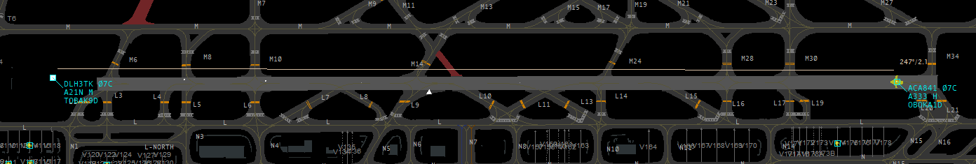
DLH3TK has reached the end of the runway and ACA841 receives the takeoff clearance; the distance is 2.1 NM, just under 1 NM less than the required separation
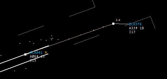
Result: The aircraft go airborne with a distance just over 3 NM - optimum separation
IMPORTANT: Always bear in mind the different speeds on take-off. If you have a C172 lead an A380 on a different SID, you could theoretically separate them by 3 NM. It should be logical that this does not make sense, as the A380 flies at least twice as fast as the Cessna and therefore, at a 3NM separation a LOS will definitely occur shortly after takeoff.
In such cases (following departure significantly faster than leading departure), it is advisable to flip the departure sequence and let the fast traffic take off as number 1. See also the article Tower Efficiency. If this is not possible and you have to send a fast departure out after a slow approach, coordinate the timing of the departure with Approach. They have the option of solving the problem by tactically using vectors or different altitudes and should let you know when you can send the fast departure on its way.
You should also pay attention to the initial rate of climb of the leading departure for "normal" airliners. Especially on the network, there are pilots who fly unrealistically fast or slow.
In general, if you are not sure about something, always ask. Especially the colleagues on APP and CTR usually have more experience and will be happy to help you
Inbounds
The handling of approaches for you as a tower controller can be explained quickly. You receive approaching aircraft from the approach controller approximately 8 - 12 NM before the runway. If you have approaching traffic on your frequency, you should give them clearance to land as quickly as possible. If you receive an approach and you have no departing traffic, you should give them clearance to land directly with the initial call. A pilot must have their landing clearance at the latest before crossing the runway threshold. If they don’t have clearance then, they will go around on their own.
The approach controller is responsible for the separation between approaches until the runway threshold is crossed. At international airports (EDDx), however, you as the tower controller may "save" the separation with the help of speed restrictions if you notice that without them, a LOS would become probable. You can also use speed instructions to maintain a gap for a VFR pilot, for example. However, it is important to coordinate speed instructions with the approach controller if there is another aircraft behind the aircraft with the assigned speed.
If two approaches are so close that there is still a risk of a loss of separation, you must instruct one of the aircraft (usually the following one) to go around before(!) the loss of separation occurs. In addition, traffic information about the traffic concerned can be useful. Further information on handling missed approaches can be found in the corresponding chapter.
Missed Approach - Controller Guide
By definition, a missed approach is the part of an approach procedure that is initiated if the approach cannot be continued for whatever reason. As this is a standard procedure and not an emergency or urgency call, every tower controller must be familiar with the handling of a missed approach.
Reasons for a missed approach
The reasons for a missed approach are complex and can be divided into two categories: Controller-initiated missed approach and pilot-initiated missed approach.
Reasons for a missed approach initiated by the controller can include
- Runway not clear: If it must be expected that a runway will not be clear when the landing traffic crosses the runway threshold, a missed approach must be instructed before the aircraft crosses the runway threshold. This also applies to situations for which the controller is not responsible (e.g. runway incursion by a pilot). Exception: Reduced runway separation is applied correctly.
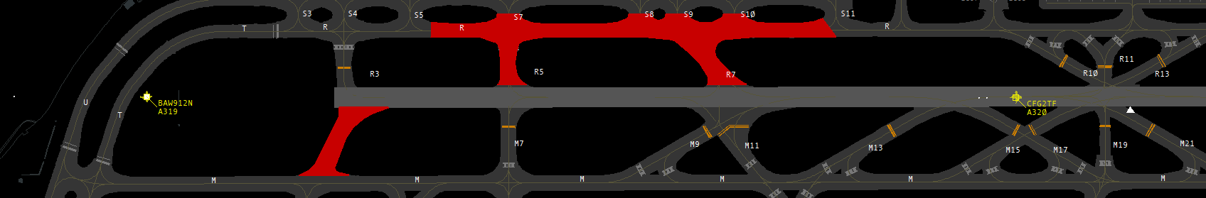 Here it is predictable that CFG2TF will not be clear of the runway in time. Therefore, BAW912N must now be instructed to execute a missed approach.
- Extended centerline not clear: At some airports (e.g. Frankfurt), certain taxiways must be clear when an inbound flies over them, otherwise the obstacle clearance is not given.
- Separation to previous approach not guaranteed: If it’s predictable that separation (wake turbulence separation or radar separation) to the preceeding traffic cannot be ensured and all other possible measures (speed reduction, delegating separation to the pilot, visual separation) have already been exhausted or are not practicable, a missed approach must be instructed. This must be done before the loss of separation occurs
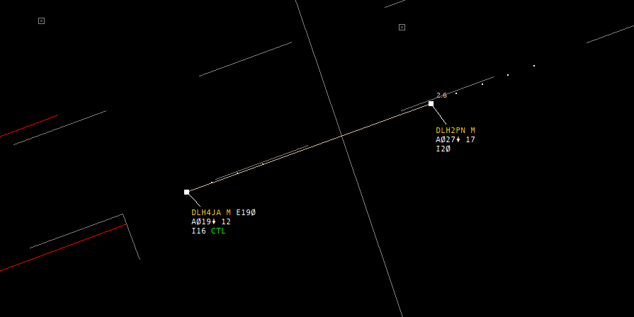 The minimum separation here is 2.5 NM. Currently the planes are still 2.6 NM apart. However, as the rear aircraft is 50 knots faster than the front aircraft, a loss of separation is predictable in the next few seconds. The missed approach must therefore be advised now.
- Separation to SVFR not ensured: If loss of radar separation to an SVFR aircraft becomes probable, a missed approach must be instructed
Reasons for a missed approach initiated by the pilot may include:
-
Unstable approach
-
Missed touchdown zone
-
TCAS RA (Resolution Advisory)
-
Wind shear on final approach
-
Thunderstorm on final approach
-
Certain errors displayed in the cockpit (e.g. landing gear problems)
-
No landing clearance received
Handling of a missed approach
First of all: A controller must assume that a pilot can perform a missed approach at any time up to and including touchdown! Still, there must always be a plan B in the event of a missed approach.
Even in stressful situations, a missed approach should be handled calmly and professionally, according to a clear plan. The steps of this plan are now explained in detail:
1. Instruct missed approach (when initiated by the controller)
- As an instructed missed approach is usually safety-critical, the controller should raise their voice on the frequency and give a clearly audible "DLH123 go around", if necessary twice in succession.
- A reason should be given briefly and concisely (e.g. "DLH123 go around, separation not ensured" or "DLH123 go around, runway blocked").
or
1. Acknowledge missed approach (when initiated by the pilot)
- If the pilot reports a missed approach, this should be acknowledged with a "DLH123, roger". The instruction to fly the published missed approach is not necessary as it is part of the approach procedure for which the pilot has been cleared.
- The first few seconds after initiating a missed approach are very stressful in the cockpit, especially in the one-man Vatsim cockpit, so no further radio messages should be sent to the pilot. Instructions relevant to separation (see point 2) are the exception.
2. If necessary, establish separation + give traffic information
-
In most cases, a pilot can fly the standard missed approach procedure and has no "opponent". However, if the missed approach brings them close to another aircraft - regardless of whether the separation is given at all times or not - traffic information shall be given.
- If separation from other traffic is not ensured, measures must be taken to establish separation.
-
-
Radar vectors ("turn away"): Upon reaching MVA, the missed approach (or, depending on the situation, other relevant traffic) may receive radar vectors, e.g. runway track, present heading or a vector to turn away. The missed approach should logically be turned away from the track of the conflicting traffic.
-
Limit altitude: Sometimes it is sufficient to keep the missed approach or a departure at a certain altitude (at least MVA) to ensure separation.
-
- In time-critical situations and only at international airports (EDDx), the tower controller may implement these measures without prior consultation with the radar controller (separation of IFR flights is delegated to the tower there). At all other airports, separation measures must be coordinated with the APP controller, if online.
-
Of course, all other traffic (other departures, VFR, traffic at the APP, etc.) must be taken into account.
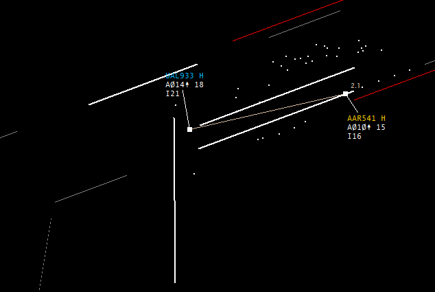
AAR541 is going around. UAL933 has just taken off and is about to turn slightly right to the northwest. To avoid entering the wakes, AAR541 should be turned to the left above the MVA (above 2100 feet) (e.g. heading 220). In addition, traffic information should be given: "AAR541, traffic, Boeing 777 just airborne runway 25C, when passing 2100 feet turn left heading 220 for separation".
- In good weather (ceiling above the MVA), a pilot can also be turned below the MVA during the day, but only for immediate danger prevention. In this case, however, "Maintain visual reference to terrain until passing [MVA]" must be added. This procedure should only be used in exceptional cases
A turn below the MVA without the above mentioned addition is a serious, safety-relevant issue and will lead to a fail in exams.
3. Coordination with Approach / other stations
-
Every missed approach must be coordinated with the approach controller (if online). Verbal coordination should always be preferred, as labeling the tag alone is often lost.
Example: "Pickup North, Tower - Go ahead - Missed approach Asiana 541, Runway 25L, flying [standard missed approach / Heading 220 due to United taking off etc.]. I don't know the reason yet. - Roger, send him to 125.355"
4. Ask the pilot for the reason and send him off
-
If the reason for the missed approach was not obvious (e.g. not instructed by the controller), the controller should ask for it. ("DLH123, report reason for missed approach"). The reason may be relevant for other air traffic (e.g. windshears - this information should definitely be passed on to following pilots) or may be of a technical nature (e.g. problems with the engine, landing gear, etc.), as a result of which the aircraft should be given priority for the next approach or be treated as an emergency if applicable.
-
As soon as the aircraft is clear of all other traffic and some time has passed since the initiation of the missed approach, the aircraft is sent away to the approach controller.
5. Pass on the reason to the APP
-
As mentioned above, there can be many reasons for a missed approach which are also important for the approach controller to know. Therefore, the reason should be forwarded to the APP controller so that he does not have to ask the pilot about it again.
Deicing using the example of EDDM
Introduction
Aircraft are becoming more and more sophisticated and complex, there are more and more plugins that are close to reality and there is more and more interest in implementing real procedures - that's why we want to deal with the topic of "deicing" here.
First of all, this is more of an "eye opener" to shed light on this topic, which is actually very interesting but has been unfairly underappreciated. As we have to go into more detail here, the text will be a little longer.
General
What is deicing and why is it important?
Frost, snow, ice and other contamination have a considerable influence on the aerodynamics of an aircraft. Just a few millimetres of contamination / ice on the upper surface of the wing can significantly influence and even disrupt the airflow and thus impact flight characteristics. Many aviation disasters are related to icing (just search for "aviation incidents / crashes deicing" on Google).
Deicing can be done mechanically (e.g. using a broom / shovel to remove snow from the wing surface) and chemically (i.e. with deicing fluid using deicing vehicles).
When do you de-ice? Only in snowy conditions, right?
There are many reasons that make deicing necessary. Very often deicing is needed even though it is not snowing at all, possibly even when the sun is shining. Here is an example: You arrive in Munich after a 6-hour flight and still have cold fuel left in the wing tanks, which are at -40°C or colder. At the turnaround you refuel for the next leg of your flight, it is +6°C in Munich and cloudy, sometimes the sun is even shining. What happens now? The warm, new fuel enters the tanks, hits the still very cold wing and a layer of clear ice forms on the top of the wing, the so-called "cold soaked wing effect" has occurred. Since, as mentioned above, contamination of the aircraft parts is not at all compatible with the aerodynamics of the aircraft, deicing can be necessary in sunny/cloudy conditions and at temperatures way above 0°C.
Who decides when to de-ice? Who actually de-ices? Who has the final say?
First of all, the PIC (Pilot in Command). They are responsible for the safety of the flight and so they decide whether to de-ice or not. Whether the wing is completely free of contamination and looks brand new and they still want to de-ice is up to them. Even if, as has unfortunately happened often enough, a rolling igloo taxis towards the runway, deicing is still the pilot's (...or the airline's financial situation...) decision.
However, as soon as an aircraft has registered for deicing, deicing is carried out by the respective airport operator or the handling agents. They alone then decide WHAT is de-iced on the aircraft and HOW. They are the last ones who inspect the aircraft and therefore assume liability / responsibility. They act according to the "CAC - clean aircraft concept", i.e. the aircraft must have been freed of any build-up and contamination after deicing. So even if there are only a few small snow residues on the fuselage of the aircraft, the entire fuselage (or at least parts of it) is de-iced, even if the PIC decides against it. He has no authority whatsoever (with the exception of technical backgrounds for special aircraft types / restrictions).
How is deicing carried out (using Munich EDDM as an example)?
A distinction is made between 1-step deicing and 2-step deicing.
In 1-step deicing, a mixture of type 1 fluid and very hot water at almost 80°C (type 1 is always orange in color) is applied to the aircraft, contamination is removed and at the same time a protective layer is applied to prevent re-icing.
In 2-step deicing, the contamination is first removed from the aircraft with type 1 and then "anti-iced" or protected in the 2nd step with type 4 fluid (cold, not heated, green in color and rather viscous).
What is Holdover time?
The holdover time, or HOT for short, is the period of time during which the aircraft is protected from re-icing. Depending on the type and method of deicing, the weather conditions, the type of aircraft (classically mainly aluminum, e.g. B737, or increasingly composite materials, e.g. B787), the deicing process used, etc., this can range from just a few minutes to several hours. Once the HOT has expired, there is no longer any reliable protection against contamination. Every (sensible) pilot will therefore want to de-ice again. However, the pilots themselves have leeway here and can still take off at their own discretion.
Where is deicing carried out?
In Munich, deicing takes place directly on the deicing pads/areas, which are located directly at the holding points in front of the respective runways. This concept makes Munich almost unique in the world (more on why this is so ingenious and why it is mentioned separately in a moment).
There are typically 3 deicing pads per active runway. In other words, for 08 operations, the intersections A1/A2/A3 at 08L are/can be used for deicing, and B1/B2/B3 at 08R. The holding points are simultaneously the deicing pads (08L A1 becomes deicing pad 1, A2 becomes deicing pad 2 etc. ... ) The same is true for 26 operations: Here there are A13/A14/A15 in the north which become the deicing pads DA13/DA14/DA15. In the south, simultaneously B13/B14/B15 etc turn deicing pads. Incidentally, you will find these on the ground charts as "DA14" = DeicingArea 14.
Propeller machines without prop brake are deiced in position, i.e. they receive apron deicing.
Why is deicing directly at the runway so efficient?
We learned above that the holdover time starts as soon as the deicing procedure begins. This is where the clock starts ticking. At airports with so-called apron deicing procedures, the clock starts ticking with the deicing procedure in the aircraft’s parking position. Then, the pilot still has to push, may additionally suffer a delay due to taxiing traffic and then we are looking at 10-20 minutes taxi time to the runway and possibly even more waiting time at the holding point. This time is wasted unnecessarily and minimizes our HOT.
The advantage of remote deicing (i.e. at the holding points) is that you can taxi to the CAT2/3 holding point immediately after deicing, do the engine runup (should be done after deicing) and take off directly. This minimizes time losses and the chance of having to de-ice again due to expired HOT is very small.
Another advantage (even if completely unnecessary on VATSIM)
In Munich, there are collecting tanks underneath ALL deicing pads. The deicing fluid / snow drains into these collecting tanks through small grooves on the deicing pad. The deicing fluid is collected, treated and can be reused, and up to 70% of deicing fluid can be completely reused. This saves a lot of money, protects the environment and the waste heat generated is used to heat an entire terminal. Pretty ingenious!
I want to de-ice! Where do I have to register?
In reality, there are many different ways to do this. Normally, pilots call in at least 20 minutes before TSAT (Target Startup Approval Time) on 121.990 Mhz (callsign "Munich Deicing Coordinator") and register there for deicing. The coordinator sees all information about the flight on their system and confirms the registration by radio. Depending on the airline, it is also possible to register for deicing via ACARS, but we are not (yet?) able to do this on VATSIM. Alternatively, you can call Tower, Ground, Delivery, Handling Agents etc. directly.
So how is deicing handled on VATSIM?
You call in at Delivery or the lowest position responsible for you and register for deicing in advance.
| Station | Phraseologie |
| Pilot | München Delivery, DLH4YA, require deicing before departure. |
| ATC | DLH4YA, request confirmed, you are in the sequence for deicing. |
After registering, you can push and taxi as normal and during the handover from apron to tower the tower will guide you directly to your designated deicing pad.
| Station | Phraseologie |
| Pilot | Tower Servus, DLH4YA, Entry S8 for deicing. |
| ATC | DLH4YA, servus, taxi deicing area B15 via S, on second radio contact decing crew on XXX,XXX Mhz, report deicing completed. |
(If, out of boredom, an ATC were to join the frequency and simulate the deicing crew for fun)
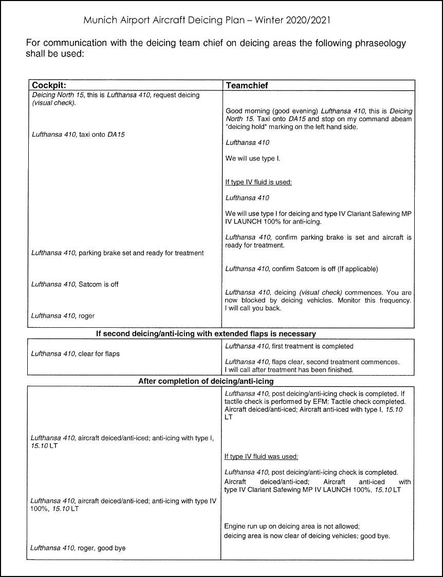
Everything else is simply improvised and simulated, that's all that's technically possible at the moment ;-) Here is an excerpt from the official document on deicing at Munich Airport, including the course of the conversation:
Crash course on METAR vs. HoldoverTime
Using the following example, I would like to briefly and roughly outline how to select the HOT / deicing variation from the tables using the current METAR information. I'll try to keep this extra short, so I won't cover every footnote or all the details:
We have the following METAR:
1820Z EDDM 26015KT 2000 -SN BKN006 OVC020 M02/M04
In short (and only very roughly!), weather report from 18:20 Zulu (i.e. in the evening), from Munich, wind from 260 degrees at 15 knots, 2000m visibility RVR, light snowfall, cloud cover at lower limit 600 ft, closed cloud cover lower limit 2000 ft, temperature -2°C, dew point -4°C.
Now I already know we don't have "active frost" alone where we can only deice / anti-ice 1 step with type 1, but we have evening / darkness, low visibility due to snowfall and sub-zero temperatures.
Since we only have RVR values (in real life we use the MOR meteorological observation range), we go directly to Table 42: SNOWFALL INTENSITIES AS A FUNCTION OF PREVAILING VISIBILITY. We know it is evening, so we go to the left column under "Night". We also know it is currently -2 degrees, so we go to the "colder/equal -1" column.
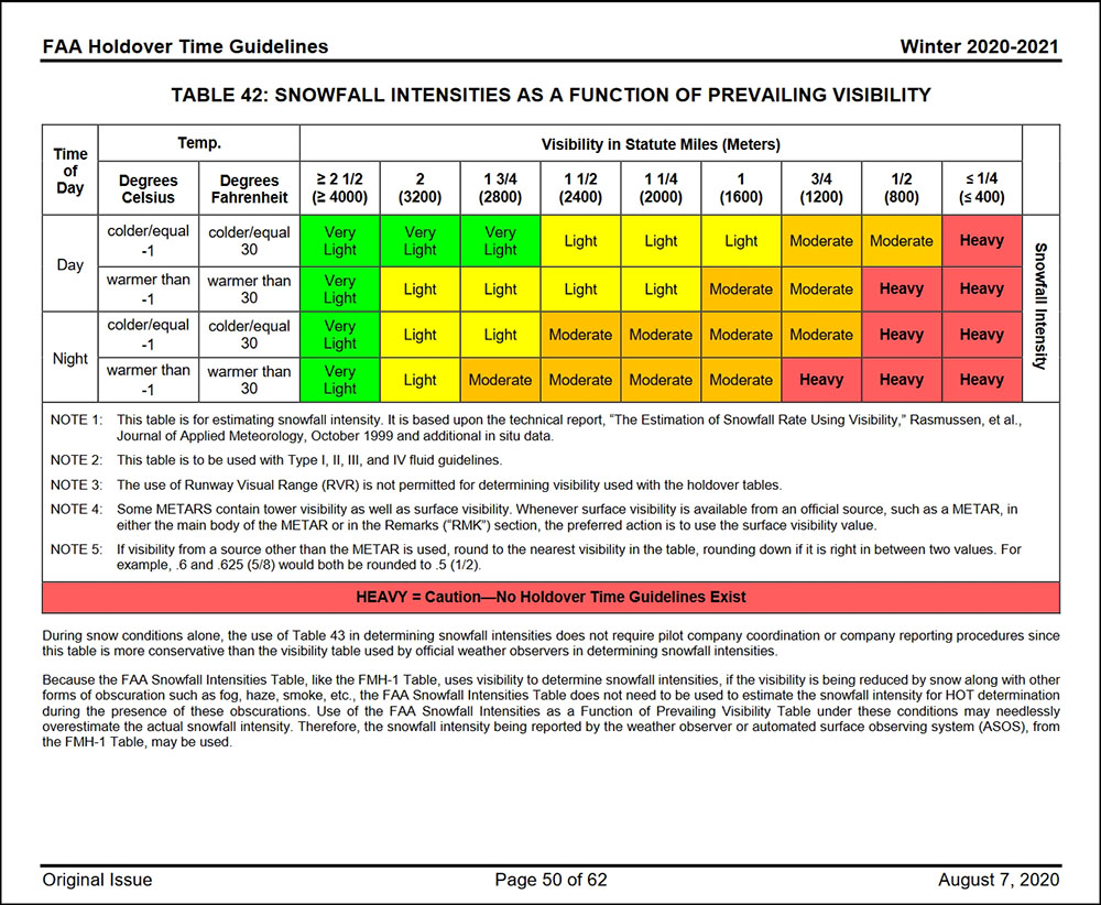
Now we take the reported visibility of 2000 m and look at the top of the column where we have to position ourselves. In our case at 1 1/4 (2000). Well, one finger to the left, one finger from above, put the two together and we end up with the value "MODERATE". Quite simple, isn't it?
With this "MODERATE" value in mind, we now go over to Table 27: Type IV HOLDOVER TIMES FOR CLARIANT SAFEWING MP IV LAUNCH (This is the deicing fluid type 4 with a concentration of 100%, which the deicing coordinator told us is what they used).

Now we continue as before: We know in the left column at "Outside Air Temperature" we have 2°C, ergo we are at "-3°C and above". We also know that the concentration is 100% type 4, so we go to "100/0" in the column.
We have previously picked out the visibility and the respective value, which was "MODERATE" and slide into the respective column to "MODERATE SNOW; SNOW GRAINS OR SNOW PELLETS"..... and get a value of 1:05 - 1:45. This means that as soon as the anticing starts, i.e. the first contact with type 4 on the aircraft, we now have a holdover time of between 1h:05 min and 1h:45 min. This will get you out of ATC pretty reliably and you still have a good time buffer. So it wasn't that difficult after all ;-)
I have attached the tables, if you want to read a bit yourself just search for the "FAA2020-2021 Holdover Tables".
This should give you a rough insight into the world of de-icing, why it is so important, what is behind it, how it roughly works and what approximate processes are behind it. Xplane, FSLabs and the Majestic Dash Q400 already simulate icing, GSX and Co. allow you to de-ice yourself and the developers of aircraft are picking up this topic more and more.
We (RG Munich) are always happy to answer any queries, suggestions, technical questions or discussions! This thread may be expanded if necessary. Spelling mistakes and other errors can be collected and exchanged for an ice cream.
Epilog
This article was created by Florian Weingartner, RG Munich, who kindly agreed to transfer it to the Wiki.
Low Visibility Operations (LVO)
The correct use of LVO is not a mandatory part of S1 training.
Introduction
In normal operations, pilots fly an ILS approach up to the so-called CAT1 minimum which usually sits 200ft above the runway threshold. Not later than at the minimum, the crew must have certain runway markings or the runway lighting in sight in order to be able to continue the approach. If this is not the case at the minimum, the aircraft must go around. ILS (and more recently also GLS/GBAS) CAT2 and CAT3 approaches are therefore available for poor weather conditions. In order for these to be carried out, the aircraft requires certain equipment (e.g. a radio altimeter), the crew must be trained and approved for this and the airfield must have a correspondingly precise and approved ILS system. In addition, the provision of CAT2 and CAT3 procedures requires certain operational procedures on the part of air traffic control and the aerodrome operator. These are explained in the following chapters. If CAT 2/3 procedures are activated, this is referred to as Low Visibility Operations (LVO) or Low Visibility Procedures (LVP).
Requirements and activation
LVPs are active as soon as one of the following two criteria is met
- Ceiling < 200 feet
- Runway visual range (RVR) <= 600 meters
The ceiling is the lowest cloud base with a coverage of more than 50%, i.e. BKN or OVC. Sometimes no cloud base can be measured (e.g. due to dense fog). In this case, the vertical visibility is used. This is given in the format VVxxx. Here are a few examples:
- VV010 = vertical visibility 1000 feet
- VV002 = vertical visibility 200 feet
- VV/// = Vertical visibility not measurable. This value is to be interpreted as vertical visibility less than 100 feet
The runway visual range is a value determined by a measuring system that differs from the ground visibility determined by a weather observer. In terms of horizontal visibility, only the RVR is relevant for the provision of LVOs. Further information on RVR can be found here.
The following rules apply to airports with several runways: LVOs always affect the entire airfield. Even if the RVR is well over 600 meters on one runway but 550 meters on the other, Low Visibility Procedures apply to all runways and taxiways.
Measures for LVO
Switch ATIS
Clear only up to CAT 2/3 holding points
Both the localizer and the glideslope signal are electromagnetic waves in the MHz range and are therefore subject to the physical phenomena of interference and reflection. The signals can be altered by sources of interference, resulting in so-called bends or scalloping. For CAT1 approaches, pilots can visually detect possible major inaccuracies in the signal below the minimum and then initiate a missed approach or manually correct the approach and land. This is not possible for CAT2/3 approaches, which may not have a minimum at all. Sources of interference must therefore be eliminated where possible.
As large metallic objects, aircraft on the runway are also sources of interference. Accordingly, they must have a certain distance from the runway in order to keep the ILS signal as precise as possible. This particularly sensitive area around the runway is called the "sensitive area" and must be free of obstacles and sources of interference.
The "normal" CAT 1 holding points lie within this area, which is why other holding points are necessary for LVPs. These are the so-called CAT 2 holding points. On ground radar maps, you will generally find two holding points at the takeoff intersections. The CAT 1 holding point is closer to the runway, the CAT 2 holding point a little further away.
Accordingly, the following phrase must be used on the radio when clearing to the holding point: "DLH414, TAXI TO CAT II HOLDING POINT RUNWAY 26R via N A15".
Correspondingly, during LVP the runway is only considered vacated by an arriving aircraft when the aircraft is completely behind the CAT 2/3 holding point. Otherwise the runway is not considered clear in terms of separation.
At some airports, the Landing Clearance Line (LCL) procedure is permitted. In this case, the runway is considered cleared when the aircraft has completely overrun the so-called landing clearance line (usually located 102 m from the center of the runway). This procedure is sometimes even more restricted (e.g. only for WTC M or L). Details on whether the procedure is permitted at your airfield, where the landing clearance line is located and how to work with it can be found in the SOP of your training airport.
Important: Depending on the SOP of the respective airport the sensitive area must be clear when the next approach reaches the 2-mile final approach. If the sensitive area is not clear when the following approach is at 2 miles, the approaching aircraft must be instructed to go around. When using the Landing Clearance Line procedure, the Landing Clearance Line must be crossed before the following approach is at 0.6 NM final approach or 200ft AGL. Whether these procedures are used on Vatsim can be found in the respective tower SOPs.
Tell the RVR
Not every RVR allows for legal landings. This depends on various factors. These include the certification of the airline, the aircraft, the crew, but also the type of approach. In order for a pilot to know whether he is currently still allowed to land, he must receive the latest RVR at two points in time:
-
At the approach clearance (by the approach controller): "DLH123, cleared ILS approach runway 25L, RVR 800 meters"
-
Before the 4 NM final approach again (can also be given with the landing clearance): "DLH123, RVR runway 25L 600 meters, wind 210 degrees, 4 knots, runway 25L cleared to land"
As there is no source for live RVRs on VATSIM, the RVR is read out of the METAR instead. Sometimes it is also possible that there is only one RVR for the opposite direction (e.g. 08R instead of 26L) in the METAR. This is then used. If there is no RVR at all in the METAR for a particular runway, it can be assumed that the RVR is greater than 2,000 meters.
Discontinuation of certain procedures
Some procedures depend on aircrafts’ visual contact or that the tower controller sees the aircraft from his window. We also simulate this on Vatsim in good weather. However, at least under LVO, the visibility is so poor that the following procedures are no longer permitted:
-
Conditional line-ups
-
Multiple line-ups
-
Reduced runway separation (limits are already higher)
-
VFR / SVFR (limits are already higher) - exception: pilot confirms that he is simulating VMC
-
Visual separation in the vicinity of aerodromes
-
Taxiing on unlit taxiways (if explained in the airport's SOPs)
Furthermore, instructions such as "Expedite taxi" or "Expedite vacating the runway" should be avoided, as it is generally not possible for the pilot to taxi faster due to poor visibility.
Approach
Radar Vectors
‘Radar vectors’ just means that an aircraft is guided by the air traffic controller through specific headings. In contrast to a standard IFR procedure (STAR, SID, Standard Approach), a so-called Minimum Vectoring Altitude (MVA) must be adhered to. This is specified for certain precisely defined areas and guarantees an obstacle clearance of at least 500 ft and sufficient radar and radio coverage. The MVA areas can be displayed in Euroscope. Values in brackets apply to the winter months.
Radar vectors can be given as heading (e.g. heading 210) or as relative turn instruction (e.g. right/left by 10 degrees). The latter should only be used if there is not enough time to request a heading. Otherwise, always work with headings.
If a radar vector is not self-explanatory (e.g. for final approach), the reason should always be given (for separation, for spacing, etc.).
Particular care must be taken when an aircraft is in a turn. In this case, requests such as: "Turn left/right by..." are completely pointless, as the aircraft in the turn can not know which heading this instruction refers to! If it is important that the aircraft turns immediately to a specific heading, the following phrase is a good idea:
DLH123 stop turn heading 180
Radar vectors for an ILS approach or localizer should be given with a heading within 30° to the final approach course. Example: Runway direction 26 - Heading for intercept 230° or 290°.
A clearance for an approach does not cancel a previously assigned speed! A new speed assignment must be explicitly communicated to the pilot.
DLH123 resume normal speed, turn right heading 220, cleared ILS 26R.
DLH123 turn right heading 230, cleared ILS 26R, maintain 220 kts to 10NM final thereafter 170 kts until 5 miles final.
The end of a STAR is the IAF, which also includes a holding pattern. This IAF automatically is the clearance limit for the approach unless the clearance limit is specified earlier in the charts.
If the pilot receives no further instructions on what to do before reaching the clearance limit, he must enter the holding pattern. It is therefore a good idea to instruct the pilot on what to do after the last waypoint as soon as the initial contact is made. The clearance to a transition waypoint (e.g. DM427) includes the clearance to continue flying the transition.
DLH123, identified, leave ROKIL on Heading 120, expect ILS 26R.
This prevents the pilots from calling when the frequency load is high and demonstrates good proactive planning!
If you want to turn a departure away from a SID, you must note that for noise protection reasons this is only permitted in Germany above 5000 ft AGL for jets and 3000 ft AGL for props. Below MVA it is totally prohibited.
Tip: A quick note on intercept headings: If strong northerly or southerly winds are known to be present, it is sometimes worth adjusting the course accordingly, i.e. shifting it by 5° or even 10°. Otherwise the pilot flying into the wind may not reach the landing course before the glide path. It makes sense to ask two or three pilots for a wind check at the beginning. Pilots seem to be flying less and less with extremely different winds in recent years (at least it feels like it). It's the exception rather than the rule and requires a little sensitivity in case someone has the wind from somewhere completely different.
Further links
- Skybrary: Basic Controller Techniques - Vectoring
- Skybrary: Vectoring Geometry
- Skybrary: Conflict Solving
- Skybrary: Basic Controller Techniques - Vertical Speed
Speeds
Used sensibly, speed control is a very helpful tool for separating aircraft and maintaining sequences.
Types of speeds
A distinction is made in aviation between different speeds:
- IAS (indicated airspeed):
The speed displayed to the pilot on the airspeed indicator. It is decisive for the aerodynamic behavior of the aircraft, i.e. how many air molecules actually flow around the wing and generate lift. In powered flight, it is generally indicated in KIAS (knots indicated airspeed) (kts=NM/h)
- TAS (true airspeed):
The speed actually flown, i.e. the relative speed of the aircraft in relation to the surrounding (still) air. The discrepancy between IAS and TAS therefore increases as an aircraft flies higher, as the air becomes thinner and thinner and the aircraft must fly faster and faster in relation to the TAS so that the IAS remains constant, i.e. the same amount of air molecules flow around the wing per unit of time. It is specified in KTAS (knots true airspeed). - GS (Ground Speed):
The speed of the vertical projection of the aircraft onto the earth's surface. This is therefore the TAS with the wind influences factored in, which cause the aircraft to fly slower over ground than the TAS if there is a headwind and faster if there is a tailwind. This is the speed displayed to the controller on the radar. - Mach Number:
Percentage of the speed of sound. Indicated with a dot and the percentage, e.g. "Mach .80" = 80% of the speed of sound. The Mach Number depends on many values, such as air density and temperature.
Similar to the rule of thumb for descents (1000 ft in 3 NM), speed reduction is approximately 10 kts in 1 NM.
Using the different speeds
Below FL280, the Indicated Airspeed (IAS) is used, as it is responsible for the aircraft’s aerodynamic behavior.
Above FL280, the Mach number is generally used, as the aircraft then become so fast that the upper limit of the possible speed is no longer determined solely by aerodynamic aspects, but also by the so-called "critical Mach number". This is the Mach number at which the first effects of supersonic air flow occur on the aircraft, causing not only turbulence but also decreasing controllability of the control surfaces. The higher the aircraft climbs, the lower its maximum IAS becomes, while the Mach number remains the same.
If speed control is used for descending aircraft, IAS can and must be used above FL280, which might easily happen at e.g. FL340.
Depending on the aircraft type, the "switching altitude" between IAS/mach/IAS can also be above or below FL280.
A change of Mach 0.01 causes a change in TAS of about 6 kts.
If necessary, the following phraseology can also be used. However, you must be aware that not every pilot will understand this instruction!
DLH123 maintain Mach decimal 80, on conversion 320 knots
Some example values at which FL is switched from IAS to Mach:
| Mach | IAS | Conversion FL |
|---|---|---|
| .82 | 310 | FL303 |
| .82 | 280 | FL350 |
| .82 | 250 | FL399 |
| .78 | 310 | FL278 |
| .78 | 280 | FL324 |
| .78 | 250 | FL374 |
| .74 | 310 | FL250 |
| .74 | 280 | FL299 |
| .74 | 250 | FL350 |
Calculations
Rules of Thumb
0.01M difference~ 6 KT GS
1000ft altitude difference ~ 6 KT GS (The higher the faster)
1 KT GS = 1 NM per hour
60 KT GS = 1 NM per minute
Distance at a certain point
Additional distance = Additional distance between 2 aircraft in NM
m = 60 minutes / flight time to the point at which the distance should exist
Additional distance * m = Speed Delta in KT
Speed Delta in Mach = Speed Delta in KT / 6
A detailed explanation of the rules of thumb is available as a video here.
Example
We have aircraft A and aircraft B at the same altitude, both leaving the sector at point P.
Aircraft A still has 150 NM (20 minutes) to point P.
Aircraft B still has 146 NM (19 minutes) to point P.
We want a separation of at least 7nm at point P. We already have a separation of 4nm, so we need to achieve a separation of an additional 3 NM (7 NM we want minus 4 NM we already have) in 20 minutes.
Now we calculate how many kts GS difference we need between the planes to reach this distance.
Since the speeds are per hour, we now extrapolate this to 60 minutes.
60 minutes / 20 minutes = 3
3 NM spacing * 3 = 9 NM spacing
Since we know that 1 KT GS = 1 NM per hour, we now know that we need a speed difference of 9 KT GS to achieve a distance of 3 NM in 20 minutes
We know 0.01M ~ 6 KT GS, so in this case we need a Mach difference of 0.02M, which will be a difference of 12 KT GS, this will lead to 4nm more difference in 20 minutes, therefore leading to a total of 8 NM (4 NM current distance + 4 NM new distance due to speed difference) distance at point P. If the aircraft are not at the same altitude, we must subtract 6 KT per 1000ft from the speed delta if the higher aircraft is the leading one. If the higher plane is following, we have to add 6 KT per 1000ft to the speed delta.
Distance after a certain time
If speed control is used, the distance after a certain time can easily be calculated:
Spacing = Speed difference / 60 per minute
As a rule of thumb, a speed difference of 30 KT (e.g. 250 KT and 280 KT) over a distance of 30 NM gives a spacing of about 3 - 3.5 NM.
Example
If the preceeding aircraft flies 30 KIAS more than the suceeding, this results in a spacing increase of half a NM per minute! Be careful if the preceedingaircraft is significantly higher than the suceeding! Remember that the TAS decreases the lower the aircraft flies. It is therefore possible that the suceeding aircraft is already flying 30 KIAS slower than the preceeding aircraft, but is still faster in relation to the GS, precisely because it is higher. It is therefore a good tactic to bring the aircraft that you want to fly slowly to the desired altitude first and then reduce the speed. If you want to maintain a high rate of descent, it is of course difficult to radically reduce speed. This should be taken into account!
When approaching an airport and holding is expected, the phrase "Reduce Minimum Clean Speed" is often used, i.e. the request to reduce to the lowest possible speed without setting the flaps. It should be noted that such a speed can always vary depending on the aircraft type and load. It can therefore not be used as a basis for relaying. The phrase "Reduce Minimum Approach Speed" should not be used!
The following rule applies on the final: On the way to the 10 NM final point, approx. 1 NM spacing is lost because the front aircraft reduces earlier. The same applies at the outer marker. You should therefore aim for minimum separation + 2 NM when vectoring so that the separation remains sufficient until touchdown!
Advanced: Ground speed effect
First of all, we need to take a look at the different speeds. The pilot has his indicated airspeed (IAS). The controller has the groundspeed (GS). The connecting element is the true airspeed (TAS). The IAS is only an indicator of how fast the aircraft is currently moving through the air. The GS is an indicator of how fast the aircraft is moving relative to the ground, corrected for influences like air density, wind, etc. This speed corresponds exactly to the speed a car would have on the ground. The TAS is a bit tricky. It expresses the speed that a solid body has in a certain medium. If we ignore the wind , we only have to deal with the solid body (our aircraft) and the medium (air) in which it is moving. At high altitudes, the air becomes thinner. This means less resistance from the medium, which leads to a higher speed of the solid body. The conclusion: the higher the aircraft, the greater the speed. These speeds are all interrelated. The TAS can be determined using a simple formula. The groundspeed is known to the controller, the indicated airspeed must be requested from the pilot.
TAS = IAS + FL / 2
Example
Let's assume that approach has received two aircraft as a package from center. Both are on the same STAR at different altitudes and there is not enough space to separate the aircraft laterally.
Our scenario is as follows: DLH123 at FL150 / 300 KIAS - CFG999 at FL160 / 300 KIAS, same lateral position, same flight direction. We now need them both at 5000ft and 3NM separation within 40NM using vertical techniques only. We assume that there is no wind, so GS = TAS
TAS DLH123 = 300 KT + 150 / 2 = 375 KT TAS
CFG999 = 300 KT + 160 / 2 = 380 KT
We need both aircraft at 5000 ft, so for DLH123:
TAS DLH123 = 300 KT + 50 / 2 = 325 KT
This leads to a speed difference between the aircraft of 55 KT (380 KT - 325 KT), so that the lateral separation increases by about 1 NM per minute (55 KT / 60 minutes).
We therefore need three minutes to separate the aircraft at the speed difference of 3 NM. We must let both aircraft descend simultaneously and one must reach our target fix three minutes before the other. What must the descent rates be in order to achieve this?
First, we calculate the descend rate of the higher aircraft. This moves at 380 KTS GS. It needs approx. 6 minutes for the 40 NM (40 NM / (380 KT / 60 minutes)) and must lose 10,000ft. This leads to a sink rate of 1700 ft/m.
DLH123 also needs 6 minutes at its current altitude and speed, but has to be there 3 minutes later than the higher CFG999. So it has to lose the 11,000ft in 3 minutes (6 minutes total flight time and the 3 minutes needed to increase separation leaves 3 minutes for the descent). This means a descent rate of about 3600 ft/m
Further links
- Skybrary: Basic Controller Techniques - Speed Control
- Youtube: Enroute Speed Control (LOVV FIR)
- Youtube: Speed Control - Rules of Thumb
Establishing approach sequences
This guide is intended to provide new approach controllers with an easy introduction to the subject. It contains the basic principles and important tips for establishing sequences on the final approach. Detailed knowledge of the articles "Radar vectors" and "Speeds" is assumed.
General
Terms
"Separation" refers to the minimum distance that two aircraft must have to each other vertically and/or laterally. Radar separation and wake turbulence separation are particularly important in this guide.
"Spacing" refers to the distance that you want to achieve between two aircraft on the final approach. This depends on many factors such as the weather, the current traffic situation, the airfield and the quality of the pilot.
In an approach sequence, we always work towards achieving the desired spacing while maintaining separation.
"Compression": As a controller, we always plan in such a way that separation is maintained until touchdown. So if we tell the pilot in front to maintain 170 kts until 5 NM before the runway, they will reduce to their final speed from this point on. In the meantime, however, the aircraft following them continues to fly at 170 kts and consequently will start to catch up. We refer to this phenomenon as "compression" or "catch-up". In most cases, it is sufficient to add one mile to the required separation to counter compression.
An example: due to the aircraft types, we need 5 NM wake turbulence separation between two approaches. We therefore add 1 NM and arrive at our spacing of 6 NM, which we maintain until 5 NM before the runway.
Finding the correct spacing
In addition to the criteria mentioned above, there is a lot more to consider in order to find the correct final approach spacing.
This includes, for example
-
The layout of the airport and runway(s) - How many runways does the airport have? Are they used for landings only or for take-offs as well? Does the runway have "high-speed exits" that allow pilots to quickly leave the runway?
-
The current traffic volume - are there currently more inbounds or outbounds? Communication with the tower is required here!
-
The weather - Are LVP in effect?
-
Pilots - If, based on your experience, you don't trust a pilot to leave the runway quickly enough, give the following pilot an extra mile. A go-around is always more inefficient than an extra mile.
-
Experience - Keep a constant eye on the situation on the ground. If the tower repeatedly fails to use a gap of 5.5 NM for a departure, give the next aircraft an extra mile.
As a general rule, a gap of 6 NM (+1 NM compression = 7 NM final approach spacing) is sufficient at most airports to allow a departure to take off.
Practical implementation
Now we have to put all this into practice.
Speed Control
Especially while starting out, It is generally advisable to set all aircraft in your TMA to a uniform speed as the work/traffic load increases. 220 kts is a good speed for this, because almost all aircraft can fly this "clean" (without flaps/slats). If all pilots are flying at the same speed, it is much easier for you to develop a plan because you can recognize the gaps laterally on the scope.
In order to allow the pilot a reasonable speed reduction, the pilots should preferably not be faster than 200kts when they reach the glideslope. Important: The approach clearance does not cancel the speed reduction. However, this is not the case everywhere. So if you are unsure whether the pilot knows this, it may be better to give them the speed again instead of finding out later that the pilot has already reduced their speed.
On final, the most commonly used values are 180 kts to 6 NM / 170 kts to 5 NM / 160 kts to 4 NM. Note: 180 kts to 6 NM in particular can lead to a less precise final approach, as pilots with different types of aircraft reduce to their final approach speed at different speeds. They will then fly even longer at different speeds than at 170 kts to 5 NM or 160 kts to 4 NM and in the end, this can lead to a difference of 0.3 - 0.4 NM
So remember: As soon as you realize your airspace filling up and you can no longer get all the planes onto the approach directly, reduce all planes to one speed early on. Try to stick to the "standard speeds", especially at the beginning, and only reduce them as you gain experience (if at all).
The correct altitude
It is also very important to descend in time. You should calculate that an airplane can descend 300 ft per NM (~1000 ft per 3 NM). As a rule of thumb, if the airplane is guided over the downwind, it should not be higher than 8000 ft abeam of the field, otherwise it is clearly too high to turn it to a 10 NM final. If you realize that the pilot is too high for your further planning, there are several ways to counteract this. You could tell the pilot the rough distance they still have to fly (see also the next chapter) so they can then descend faster or slower at their own discretion. Otherwise, you can also assign the pilot a certain descent rate. But don't wait too long, because even with speedbrakes, aircrafts’ descent rates are not limitless.
With the clearance for the approach, pilots may descend to the published altitude for the approach. If the controller wants the pilot to fly at a different altitude for the approach, this must be explicitly stated.
Achieving the desired spacing
To estimate the distance of the aircraft until touchdown, observe a plane that is already on the ILS. Then, you need to determine the spacing you currently need. If, as in the above example, you need a final approach spacing of 7 NM, start with the first aircraft and count backwards in increments of 7. So, if the first aircraft is at 13 NM, the next one, at the same speed, must fly exactly 7 NM more (i.e., 20 NM). The ones behind will need to fly 27, 34, 41 NM, etc.
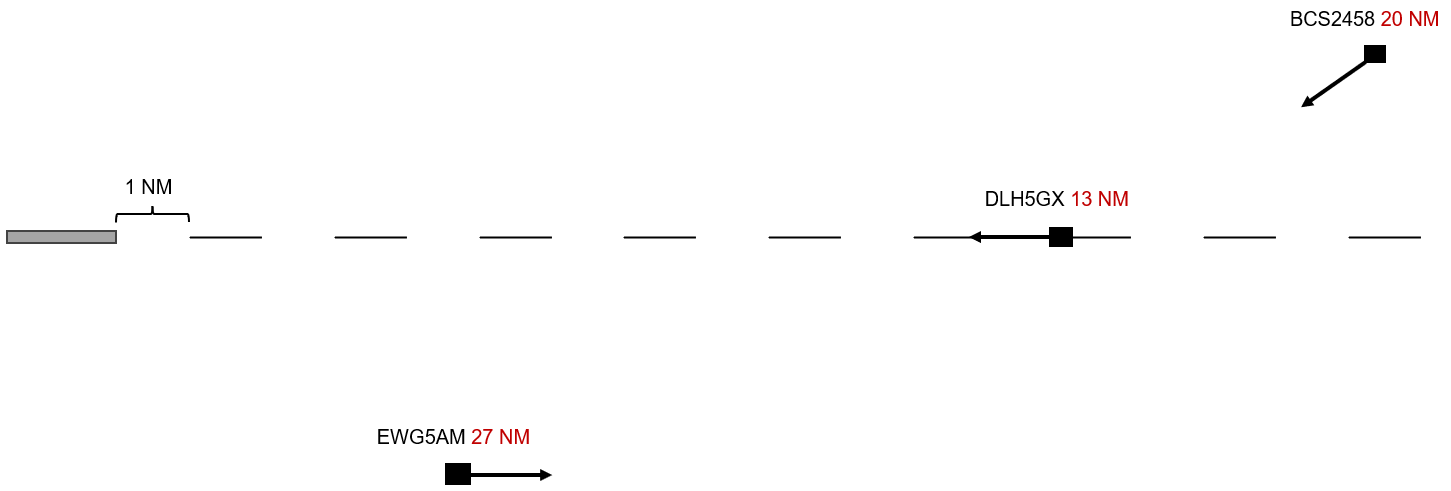
There are various ways, procedures, and tips to achieve this:
Downwind
The downwind leg runs parallel, in the opposite direction to the final approach, and should be about 5 NM away from it. Many airports already have arrivals or transitions set up like this. The planes should not exceed 220 KIAS to avoid overshooting when turning onto the final approach.
If you turn the following aircraft when the preceding one (already established on the LOC) is abeam, this will result in a spacing of 5.5 to 6 NM between the two aircraft on the ILS (Figure 1), assuming both aircraft have the same speed. This refers to the moment when the aircraft turns, not when you as the controller start speaking – you need to issue the instruction a bit earlier. If you turn the aircraft when it's 0.5 NM past abeam, you will gain an extra NM of spacing because the aircraft must "fly back" that 0.5 NM (Figure 2). Each additional NM of downwind results in 2 NM more flying distance. Turning the aircraft when it's 0.5 NM before abeam will result in 1 NM less spacing. With this rule of thumb, you can calculate any desired spacing. Experiment a little and fine-tune with earlier or later speed reductions.
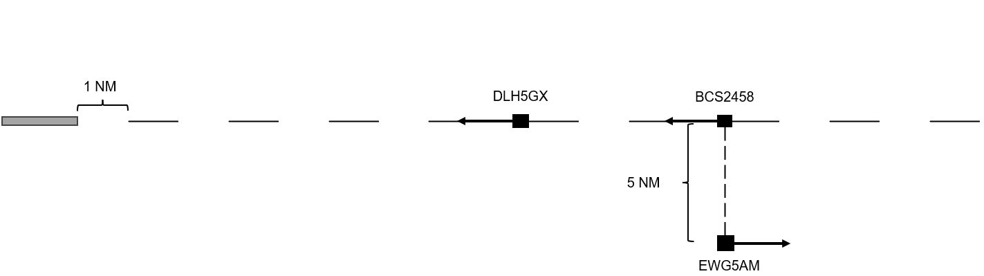
Figure 1
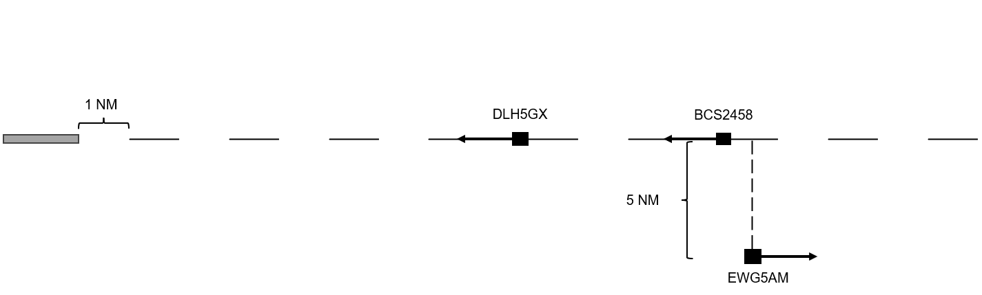
Figure 2
If the aircraft is turned onto the final approach just two radar updates (10 seconds) later than planned, it will have already covered 1 NM in that time. This means it will need to fly 2 NM more, which is rarely corrected with speed adjustments. Over 30 seconds, this results in 6 NM more flying distance and reduces the runway capacity by 50%. This example clearly shows why your priority should always be the final approach!
Base
You can use the base leg depending on local conditions and traffic to turn aircraft from the downwind onto the final approach (Figure 1) or to allow aircraft to fly more or less "directly" onto the final approach (Figure 2).
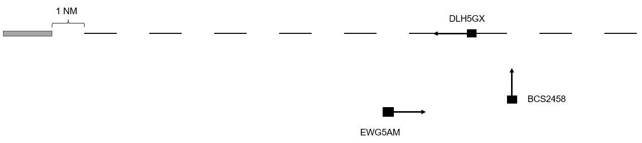
Figure 3
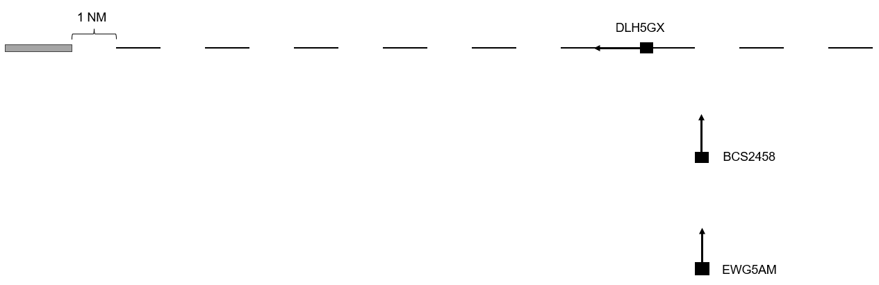
Figure 4
If you look closely at the figures, you'll see that the distance of BCS2458 (and EWG5AM in Figure 2) relative to the final approach remains constant. The only variable distance is that of the Lufthansa moving westward toward the runway. Therefore, the base leg should ideally be at an angle of 90° or more to the final approach in both cases. Otherwise, situations like in Figure 5 can occur. Here, the distance from DLH5GX to the runway decreases, while the distances of BCS2458 and EWG5AM increase. With each radar update, the spacing relative to the approach changes. This makes it much harder to accurately turn the aircraft one after the other onto the final approach.
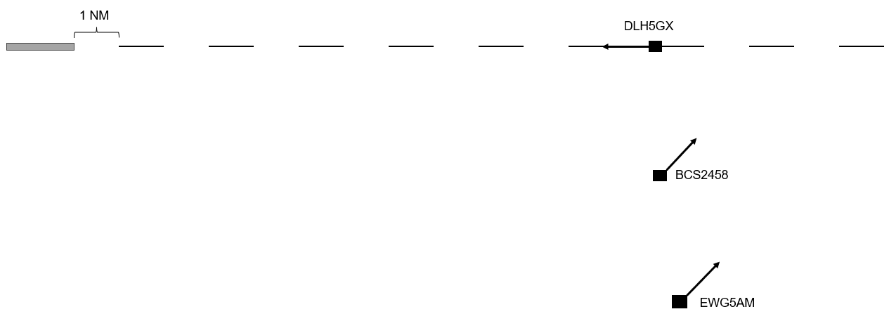
Figure 5
Final Approach
The goal of the approach controller should be to guide all aircraft onto the final approach at more or less the same point. To achieve this, it’s important that the feeder receives neither too few nor too many aircraft. In the first case, the intercept point shifts closer to the airport; in the second case, it shifts farther away.
Of course, you won’t always manage to have every plane intercept at exactly the same point. However, at most German airports, 10-15 NM is a good guideline. Generally, on Vatsim, the goal should be to have as short a final approach as possible, as this minimizes the effects of technical differences, such as wind or speed variations.
Adjustments
Slow aircraft
One of the more challenging situations is when you need to integrate an aircraft into the sequence that will fly the final approach significantly slower than the others. Here, too, you should try to let the plane fly as short a final approach as possible. Over 20 NM, a speed difference of 60 or more knots will waste much more space than over 8-10 NM. Therefore, the aircraft should always be kept near the ~10 NM final, for example, by having it fly circles. When the opportunity arises, you can then slot it in. How many miles do you need to the next aircraft? You can calculate this again using the formula:
Speed difference / 60 = loss of spacing per minute
For example, if the slow type is flying the ILS at 120 KTS and cleared for an 8 NM final, it will take about 4 minutes to reach touchdown. If the following traffic is flying at an average of 180 KTS, it gains 1 NM per minute on the slow type. Therefore, the following plane needs at least 4 NM more than the required separation to avoid catching up to the slow aircraft. In such a scenario, it’s always better to err on the side of caution and give one or two miles more rather than too few.
A further video with an interesting approach can be found here:
https://youtu.be/VNcSB-c6atU?si=Wo2vHTW9Dgm0zHE6
Wind
Wind can also affect the headings used for downwind or base legs. For an east-west runway with a west wind pushing aircraft eastward, a heading of 360° for the base leg may need to be corrected 5 or even 10 degrees to the left. A heading of 180° may need to be corrected to the right. Tools like windy.com, which show the wind at altitude, can help assess the potential effects.
In cases of strong headwind on the final approach, it’s important that aircraft are not turned too early or too late onto the final. As soon as the aircraft turns onto the intercept heading, its ground speed begins to decrease. If the trailing aircraft is turned too early, speed control will be less effective than in calm wind conditions. If the aircraft is turned too late, it becomes much harder to make up the gap with a headwind, and the aircraft will fly more distance in the final turn.
Think about the effects of wind when it’s perpendicular to the approach (e.g., from the north or south on an east-west runway). What difference does it make on the base leg when aircraft from one direction have a tailwind and others a headwind, even if all are flying at 220 kts?
Consider, before logging in, what adjustments might be sensible and observe how it works with the first few aircraft.
Pilots
With some experience, you can usually gauge whether a pilot is new and/or unfamiliar with their aircraft from the first contact. Keep this in mind when planning and issuing instructions.
Give a new pilot an extra mile or two on the final, keep in mind that their instructions may be carried out with some delay, and don’t waste time scolding them for mistakes. Focus instead on resolving the situation.
Not everything is lost because of one pilot!
Holding Management
There can be various reasons why you have to initiate a holding. One reason can be that the arrival controller can simply no longer manage to get the necessary spacing between arrivals rushing in. Holding is then used as a means of creating spacing.
Another possible reason is that the approach controller stops accepting any more aircraft because, for example, the runway is closed.
Initiating a holding pattern
Holding is always managed by the CTR controller. If you know that you have to initiate a holding pattern, you usually slow down all aircraft still flying towards the holding fix to "minimum clean speed" so that they have to spend as little time as possible in holding. This is more economical.
It is important to make sure that all aircraft arrive at the holding fix with a 1000 ft separation, so ideally you would work with rates in descent.
HOLD AT / OVER (significant point, name of facility or fix) MAINTAIN / CLIMB / DESCEND (level) *(additional instructions, if necessary)* EXPECT FURTHER CLEARANCE AT (time) / IN (minutes) / EXPECTED APPROACH TIME (time)
The pilot should always be informed where and how high to fly into the published holding pattern. In addition, an expected approach time (EAT - Expected Approach Time, i.e. time when to leave holding) must be calculated if a stay in the holding patternof more than 20 minutes can be expected and be communicated to the pilot together with the holding instruction. For military aircraft (1-2 seater jets), the EAT must always be added regardless of the 20 minutes, as they generally calculate their fuel very tightly and may have to divert directly to the alternate. In addition, the pilot must always be informed if a new EAT deviates from the previous one by 5 minutes or more.
DLH123, hold over SPESA, maintain FL130, expected approach time 1230.
In addition to the ‘general holding instruction’ shown here, there is also a ‘detailed holding instruction’. This contains the following points:
- holding fix
- holding level
- inbound magnetic track to the holding fix
- direction of turns
- time along outbound leg or distance values, if necessary (up to FL140 1 minute, at or above FL150 1.5 minutes)
- time at which the flight can be continued or a further clearance can be expected
It is standard procedure to give general holding instructions unless one of the following points is met:
-
The pilot follows a holding procedure other than the published one
-
The pilot reports that he does not know the published holding procedure
-
The pilot must enter holding over a point for which no holding procedure is published
The callsign and altitude can be highlighted in color in the tags when using Topsky to make it easier to see the aircraft in holding patterns.
Holding capacity
Incidentally, a holding pattern should not be assigned too high. If so many planes have to hold that the holding stack would be reach above FL200, you have to think about opening a second holding which has to have enough distance from the first one. This is often referred to as "enroute holding". If this is no longer possible in your own sector, the adjacent center sector must open a holding, as no more inbounds can be transferred from them to you.
Terminate holdings
Having the aircraft all circle in the holding pattern does of course not really present a challenge, but it becomes a real art as soon as the approach controller starts receiving airplanes again and you have to hand them over to them with a 10 NM spacing. Handing the whole holding stack over to APP so the controller can take airplanes out of the holding on their own only makes sense if the APP has at least the lowest 3-4 planes on their frequency. This is the only way they can get the airplanes into a sequence without wasting a lot of space. Ideally, CTR manages the exit from the holding pattern and only then hands the aircraft over to APP (coordination may be required for where CTR should clear the planes to).
Letting each aircraft complete its holding and only then continue clearing them to APP definitely is a bad tactic. Doing this makes the 10 NM spacing you are aiming for an absolute coincidence, if it works at all.
To improve this, you have to think ahead a lot: you have to instruct the next aircraft to leave the holding well in advance to stay on the outbound heading, on the "downwind" of the holding pattern, so to speak. Once it is shortly beyond the abeam point to the preceding traffic (which is already flying towards the holding fix, i.e. is virtually in the "final" of the holding), you simply turn it in behind it and you should get pretty much exactly 10 NM out of it. We aim for so much more spacing than when vectoring to the ILS because the aircraft are always significantly higher and therefore have a higher GS (although they are also flying at approx. 220 KIAS). At this point, the corresponding measure for the aircraft following the aircraft that has just turned back to the holding fix also has to have been initiated already. These holding patterns and their management really have a lot to do with advance planning.
It is also very important to always quickly follow up with the cleared levels. As soon as a plane has left the holding, you clear the plane above it down to this now clear level. You can then have it report reaching this level, for example, so that you can immediately move the plane above it and do not forget to keep the cascade of airplanes being cleared down to the cleared levels below them moving.
"Clearing out" a holding is therefore almost the same as feeding to the ILS. There is a downwind and a final, but you also always have to make sure that the airplanes are instructed to hold the outbound heading well in advance, because if you miss it once, you will lose quite a few miles.
Holding Times
Holdings should only be used for as long as necessary to avoid arrival running empty. APP and CTR must coordinate how long the aircraft need to be delayed. Often just one lap in the holding pattern (about 4 to 5 minutes) is enough to make sure that enough capacity is available again.
It helps to consider or measure when the last aircraft is on final at APP. Taking into account the remaining distance for the inbounds, the reduction of the holding can be planned.
Further links
- Skybrary: Holding Pattern
Low Visibility Operations (LVO) - Arrival
In case of low visibility conditions, the controller has to adapt the procedures at the airport to ensure a safe continuation of flight operations.
However, controllers do not differentiate between CAT II and CAT III operations. The pilots must decide for themselves which approach they can fly based on the prevailing RVR and ceiling.
Low visibility operations become active when the runway visual range (RVR) is equal or less than 600 m and/or when the ceiling (BKN / OVC) is below 200 ft or when there is no vertical visibility.
The separation between two approaching aircraft or one approaching and one departing aircraft must be increased compared to standard operations so the ILS signals are not disturbed by approaching and departing traffic or by taxiing aircraft or vehicles on the ground.
Approaches must be given the prevailing RVR together with the approach clearance. Which ILS category is used is up to the pilot and is therefore not mentioned in the clearance.
DLH123, turn left heading 220, cleared ILS runway 25L, RVR 300 metres.
Depending on the volume of traffic, it may be necessary to increase the spacing between approaches to avoid missed approaches.
Center
Conflict detection
Definitions
Conflict. Predicted converging of aircraft in space and time which constitutes a violation of a given set of separation minima.
Conflict detection. The discovery of a conflict as a result of a conflict search.
Conflict search. Computation and comparison of the predicted flight paths of two or more aircraft for the purpose of determining conflicts.
Source: ICAO Doc 9426
Description
Detecting conflicts between aicraft is an important part of the air traffic controller job and arguably the most complex one. Once a conflict is properly identified the resolution is relatively straightforward - the controller chooses an appropriate method (e.g. level change, vectoring, speed control, etc.), implements the plan and monitors aircraft compliance. If the situation remains undetected, however, this may result in loss of separation, late (and more abrupt) manoeuvres, STCA/TCAS activation or worse.
If all aircraft are assigned different levels, and are not expected to climb or descend, then there are no conflicts. Most commercial operations however take place in the RVSM layer which means that this situation is unlikely. Therefore, normally the first thing to be done in a surveillance environment, is a "same level scan", i.e. looking for aircraft that are maintaining the same level. This initial step identifies aircraft that need further examination. The second phase is to discard the pairs that are "obviously" non-conflicting, e.g. flying at the same speed to the same point with long distance between them, those whose paths do not cross, etc. After that, the minimum distance of the "suspicious" pairs is determined and, if necessary, a plan for solving the conflict is created.
Climbing and descending flights present a special challenge as they require more checks to be done, e.g.:
- Does the current level cause conflicts?
- Will the final level for the sector cause a conflict (within the sector or at the exit point)?
- Will any of the intermediate levels cause a conflict within the sector?
- Will the aircraft be able to reach its planned level before the exit point? If not, will this cause a conflict in the next sector?
These checks may become more complex if the aircraft climbs or descends through a high number of flight levels (e.g. climbing from FL 140 up to FL 360). This results in significant change in groundspeed (due to wind and IAS variations) which hinders precise calculations.
Factors that help controllers detect conflicts are:
- system support (see section below)
- discipline, i.e. performing structured scan of the aircraft that are, or will be under control and evaluation of the impact of each flight profile change
- fixed-route environment. This usually means that there are fixed "hotspots" (normally where airways cross). An experienced controller can often detect a conflict by knowing that when there is an aircraft at point A then if the other one is at point B they will be in conflict at point C.
- recurrent training for non-routine situations
Factors that may cause a conflict to be missed include:
- Strong winds (e.g. 50-100 kt or more). These may alter aircraft speeds in such a way that a BOEING 737-300 becomes faster than a AIRBUS A-380-800 in terms of groundspeed. Also, aircraft flying at different tracks will be affected differently. As a consequence, pairs that seem to be safely separated may be in conflict.
- Free route environment. This means that the "standard" hotspots are no longer relevant and a situation may arise anywhere. While free route generally reduces the number of conflicts it makes them harder to identify.
- "Irregular" aircraft, i.e. such that form a small fraction of the traffic flow and can be overlooked due to e.g. high workload or complacency. Examples of these are non-RVSM aircraft in RVSM space, slow-flying business jets, slow-flying aircraft at lower levels (interfering with arriving and departing aircraft), non-routine situations (e.g. aicraft dumping fuel, military interception), etc.
- Deviation from procedures, e.g. provision of ATS outside the area of responsibility, skipping "unnecessary" coordinations, etc.
- Aircraft avoiding weather are a special challenge, because their behaviour is less predictable and trajectory updates cause increased controller workload. If the controller does not update these, however, system support tools may be less useful.
- Airspace boundaries are areas where conflicts are sometimes detected late. This can be caused e.g. by poor coordination, improper colour representation, etc.
- Blind spots - a controller may examine the future path of an aircraft failing to notice the conflicting one which is just above (or below)
- Improper handover/takeover. The relieving controller normally expects all conflicts to be solved or at least detected and having a planned solution. If this is not the case, or if the controller being relieved fails to pass the information, it is possible that the new controller focuses on the medium and long-term situations and misses a near-term conflict.
source: www.skybrary.aero
Conflict Solving
This article describes the typical methods and controller actions used to solve conflict between aircraft in a surveillance (mostly en-route) environment. Only situations with two participating aircraft are considered. Although more complex scenarios (involving three or more aircraft) do exist, they happen rarely and in most cases can be considered as multiple two-aircraft cases that happen at the same time.
In broader terms, a conflict is a situation where the separation at the closest point of approach will be less than the specified minimum and one of the following exists:
- Two aircraft are flying at the same level. In this case, doing nothing will result in a Loss of Separation. There are two sub-scenarios to this:
- Crossing conflict - the two aircraft's paths cross at some point and diverge afterwards.

- Converging conflict - the two aircraft's paths join at some point and remain the same afterwards, at least for a portion of the flight.

- Crossing conflict - the two aircraft's paths cross at some point and diverge afterwards.
- At least one of the aircraft is climbing or descending to a level that will make it cross the other aircraft's level. In this case, doing nothing may lead to a loss of separation depending on the circumstances (e.g. vertical speed, distance between the aircraft, current vertical separation, etc.)
- The two aircraft are vertically separated but at least one of them needs to be cleared to a level that would cross the other's level (e.g. due to reaching the top of descent). Here, doing nothing will not cause loss of separation. However, improper timing of the instruction to change level may lead to this.
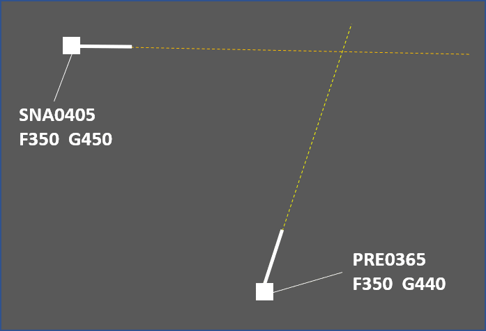
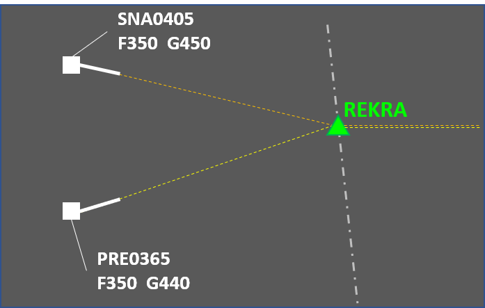
The second and the third situation usually happen near the transition between approach and area control. This is where departing aircraft reach their cruising level and arrivals start preparation for the final portion of the flight. The first one is more typical to the cruising part of the flight.
Action to be taken by the controller in order to eliminate the risk of separation breach depends on a number of factors such as the type of conflict, the specific circumstances, the available aircraft performance, controller workload, etc. The most common methods for solving conflicts are:
- Level change. This solution is typically used for conflicting aircraft in level flight. In the crossing case, an opposite level may be used for a short time and then the aircraft will climb again to its cruising level. This is not an option in the converging scenario, meaning that the level change needs to be at least 2000 feet. Sometimes it is possible to use opposite levels for converging conflicts but this requires coordination with the downsteam sector or unit.

An example of using a 1000 ft level change to solve a crossing conflict - Speed control. This method is mostly suitable for solving medium-term conflicts (as the instruction takes time to "produce" separation) and for maintaining already achieved separation. A major limiting factor is the typical cruising speed. For example, trying to sequence an AIRBUS A-380-800 behind a BOEING 737-800 would likely be impracticle (though not impossible). Additional factor to consider with speed control is that the results are not as obvious as for example with level change or vectoring. This means that the controller will need to monitor the situation more frequently to make sure that (a) the flight crews comply with the instructions and (b) the speeds are not affected by changing winds. On the other hand, this method normally results in the slighest intervention of the flight plan - the trajectory and vertical profile are not changed.
- Vectoring. This is a universal method that may solve any conflict unless additional factors (such as airspace restrictions or adverse weather) limit the available headings. This benefit comes at a cost, however - vectoring usually extends the distance flown (and hence, delays the flight). This effect may sometimes be mitigated by providing a direct routing after the conflict has been solved.
- Direct routing. This method is somewhat similar to vectoring because it relies on the aircraft track being changed to an extent where the horizontal separation will no longer be reduced below the minimum. While this method has limited applicability (the results depend mostly on the flight planned route) it often contributes to flight efficiency by reducing the distance to be flown. Other benefits are that the results from the controller intervention are immediately visible and that a single message solves the conflict altogether (unlike with most other methods that follow the instruct-monitor-resume routine). There are some downsides to this solution however, e.g.:
- Depending on the specific circumstances, the flight may enter an area with strong headwinds (which the pilot tried to circumvent with the longer flight planned route).
- In most cases the flight needs to be cleared to a point that is far away which in most cases means a coordination with the next sector or unit will be necessary. This increases controller workload and also adds an element of uncertainty (the next sector controller may not approve the direct routing).
- A direct routing may solve one conflict but create another at the same time.
- Vertical speed adjustment. This technique is used in situations where an aircraft needs to safely cross another aircraft's level. If properly used, it provides safe and efficient flow of traffic. The rates of climb or descent to be assigned need to be carefully calculated to accomodate some non-compliance (e.g. if the controller assigns a rate of climb of 1500 feet per minute or greater but the aircraft actually climbs at 1300). Also, while descent rates are usually achieveable, climbing at a specified vertical speed may be outside the aircraft capability and therefore the restriction should be coordinated with the flight crew.
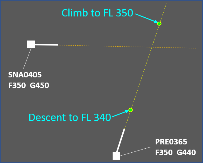
A combination of the methods above is sometimes used. Here are some examples:
- Using vectoring to ensure horizontal separation is maintained and assigning vertical speed so that vertical separation is achieved faster (and the vectoring may be terminated sooner). This is useful for separating departing and arriving aircraft.

An example of using vectoring and vertical speed control. Turning PRE0365 provides safety and assigning vertical speeds results in efficiency as the flight can be returned onto the flight planned route sooner. - Combining vectoring and speed control may result in a smaller overall intervention as opposed to using vectoring only.
- Combining a direct routing (that makes the converging conflict a crossing one) with a level change. The benefit is that 1000 ft temporary level change may be sufficient as opposed to 2000 feet change for a longer period of time. Note that the direct routing may need to be coordinated.

An example of using a direct route and a level change. Initially, the conflict is of the converging type. By clearing the yellow aircraft to fly on a direct route, the controller does not solve the conflict but now has the option to use 1000 ft level change for a few minutes as opposed to 2000 ft until point MIDLE.
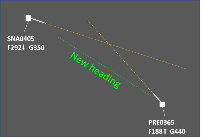
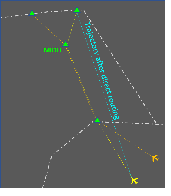
Combined solutions need to be carefully considered. These usually increase the flight crew workload. In some cases the instructions may even be incompatible. An example of this is assigning a high rate of descent to an aircraft that has already been instructed to reduce speed.
Source: www.skybrary.aero
Vectoring
This article describes the use of vectoring by air traffic controllers to manage the traffic flow and resolve conflicts. It is focused on the en-route phase and describes the general principles, typical uses and associated risks. The article also gives some advice about the practical use of the vectoring method. Note that the advice is based mostly on good practices and experience, and is in no way intended to replace or supersede local procedures and instructions.
Description
The goal of vectoring is to have the aircraft achieve and maintain the desired track. When an aircraft is given its initial vector diverting it from a previously assigned route, the pilot must be informed about the reason for the deviation (e.g. due to traffic, for sequencing, etc.).
General restrictions:
- Aircraft must not be vectored closer than a half of the separation minimum (i.e. closer than 2.5 NM if the separation minimum is 5 NM) or 2.5NM, whichever is higher, from the limit of the airspace which the controller is responsible for, unless otherwise specified in local arrangements.
- Controlled flights are not to be vectored into uncontrolled airspace, except in the case of emergency or in order to circumnavigate adverse weather (in which case the pilot should be informed), or at the specific request of the pilot.
- When vectoring or giving a direct route to an IFR flight takes the aircraft off an ATS route, the clearance should take into account the prescribed obstacle clearance.
After vectoring, the controller must instruct the pilot to resume own navigation, giving them the aircraft’s position if necessary.
Typical uses
- Flight Identification - while not common in e.g. European airspace, this is one of the few methods for identification available when only primary radar is used.
- Navigation assistance - if due to equipment malfunction other navigation means (e.g. GNSS, INS, RNAV) are not available vectoring remains an option. This can also be useful for strayed VFR flights if the pilot has lost orientation.
- Special use area (SUA) bypassing - if for whatever reason a flight is approaching a SUA (prohibited, restricted, danger, temporary segregated, etc.) and flying above or below it is not feasible then vectoring may be used to guide the aircraft around it.
- Conflict solving (opposite) - if a level change is not possible for some reason (e.g. aircraft unable to climb, conflicting traffic at other levels, need for coordination with other sector, etc.) vectoring can be a very efficient way to solve the situation. A relatively small change of heading is often enough to achieve the desired separation.
- Conflict solving (crossing) - vectoring is a very effective method for solving crossing conflicts if a level change is not preferable and there is not enough time to perform speed control. In most cases, the aircraft that comes second to the intersection point of the two tracks is instructed to turn in the direction of the first one ("aiming for the other traffic"). This manoeuvre effectively puts the second (or slower) aircraft well beind the first (faster) one. After the crossing is complete, the vectored aircraft may be resumed to point that would compensate for the deviation and the extended flight path, thus gaining both safety and efficiency.

- Sequencing - often combined with speed control, vectoring is an effective method to achieve the desired distance before reaching the boundary with the next ATS sector or unit. The application is similar to the crossing scenario, the difference being that after the desired separation is achieved the aircraft being vectored remains behind the one that is ahead.

Choosing the aircraft
When vectoring is chosen as a means to solve a conflict, the first task of the controller is to decide which aircraft will have to change its heading. Generally, there are three situations:
- Vector both aircraft. This is mostly used to solve conflicts of aircraft on reciprocal (opposite) tracks. This method increases the controller workload (due to having more communication exchanges on the frequency) but offers the benefit of less impact on each aircraft trajectory. Consequently, the increase of the distance flown is usually negligible. While turn direction is determined based on other factors (see next section), the general idea that both aircraft turn, and in the same direction, remains.

- Vector the aircraft that is behind. This is usually used when the two aircraft are maintaining altitude and one is considered to be overtaking the other. This is the more convenient choice from ATC perspective as well, since it requires less intervention (there is already some separation).

- Vector the requesting aircraft. If a pilot makes a request (usually to climb) and accommodating this request would result in insufficient separation with another aircraft, then the general choice is to vector the requester. Sometimes two vectors are used in such situations - the first one to achieve the desired separation and a second one to maintain it by flying on a parallel track.

Turn Direction
After the aircraft to be vectored has been chosen, the controller decides the direction of the turn. The following general principles are used:
- Aircraft flying on opposite tracks are turned in a direction that would increase the separation.

Turning Aircraft 2 slightly to the right is enough to solve the conflict while turning it to the left, even by more degrees, does not. - "Aiming" at the first aircraft's current position. The crossing point is moved in such a way that the distance from the first aircraft is reduced significantly while the distance from the second one is reduced marginally. This results in the second aircraft passing further behind.

Turning Aircraft 2 to the left solves the conflict by placing it behing Aircraft 1. A vector to the right, while prolonging the time to the conflict, does not solve it. - Turning an aircraft against the wind. This reduces the ground speed, effectively placing the aircraft being vectored further behind. In some situations, if the wind is strong enough, vectoring against the wind can be much more effective than speed control for sequencing purposes.

Turning Aircraft 2 to the right allows it to safely climb to FL 350. Due to the speed reduction caused by the wind Aircraft 2 can be sequenced behind Aircraft 1. - Turning in a direction that is in line with the flight planned trajectory is preferable. Thus when the aircraft resumes own navigation its overall flight distance will be only marginally increased and may even be reduced (compared to the flight planned).

Vectoring Aircraft 2 in any direction would solve the conflict but the left turn would not cause a delay. - Turning away from other traffic, special use areas and sector boundaries when practicable. Otherwise additional controller actions may be necessary (e.g. coordination, solving other conflicts, etc.).
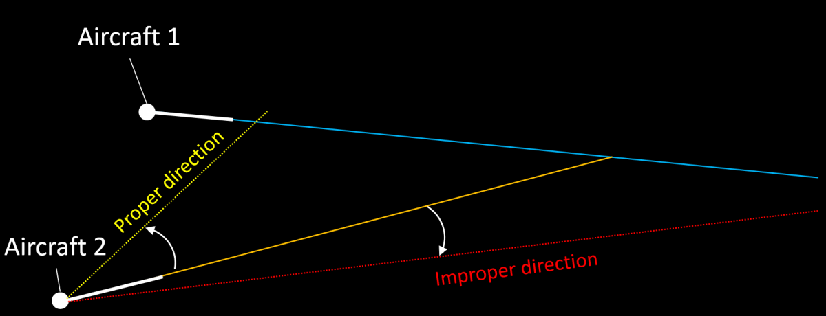
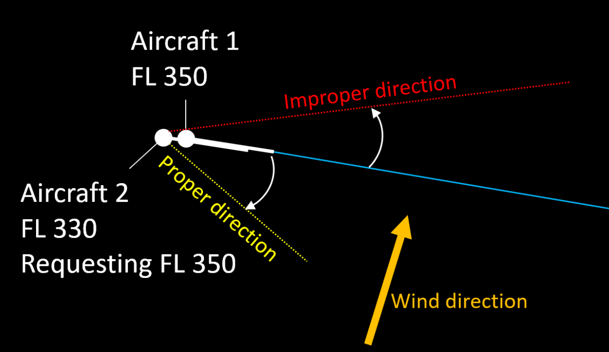
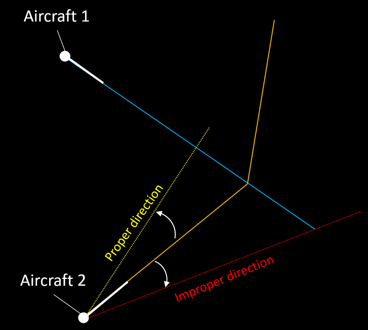
Associated Risks
- Forgetting that an aircraft is being vectored. This has a negative impact on flight efficiency but may also "surprise" the next ATS sector or unit, especially if the airway makes a sharp turn at the transfer of control point and the aircraft does not.
- Miscalculation of wind impact (level flight). If a controller tries to sequence an aircraft after another one by vectoring but instructs it to turn so that the tailwind component increses, then the manoeuvre may have no effect (the tailwind will increase the aircraft's speed effectively reducing the expected benefit from vectoring).
- Miscalculation of wind impact (climbing and descending aircraft). Wind may be different at different levels. Even if the direction is somewhat the same, the windspeed can vary significantly. Consequently the headwind/tailwind/crosswind component will also vary and this may impact the desired result. For example, the drifting angle at different levels may be different if the windspeed (and therefore the crosswind component) increases with height. This may lead to parralel tracks becoming converging. A common mitigation for this is to assign a parallel or slightly diverging heading to the aircraft being vectored.
- Miscalculation of aircraft performance (climbing and descending aircraft). Generally, climbing aircraft increase their groundspeed and descending aircraft reduce it. The speed at cruising level can be twice that at e.g. FL 150. If this is not taken into account properly, the result may be loss of separation.
Things to consider
- Crossing point. In most cases vectoring is used to solve crossing conflicts. It is usually most efficient to turn the aircraft that would reach the crossing point later and in the direction of the other aircraft, i.e. if the conflicting traffic is to the left, then the turn should also be to the left. The manoeuvre effectively places the aircraft being vectored behind the other one. If for some reason the first aircraft needs to be vectored, this would require a much larger deviation.
- Closest Point of Approach (CPA). This is the moment when the distance between the two aircraft reaches its minimum. It should be noted that in general, the separation between aircraft continues to reduce for some time even after the first aircraft to reach the crossing point has crossed the track of the second one. The difference between the separation when the first aircraft reaches the crossing point and the moment of CPA depends on the conflict geometry. For example, if the tracks cross at right angle and both aircraft fly at the same ground speed then the separation at the CPA will be about 70% of the separation at the crossing point.

- The sooner, the better. An instruction given well in advance will have (almost) no impact on flight efficiency while solving the situation safely. For example, even a 5 degree heading change would result in about 6 miles displacement to the left/right after 10 minutes. On the other hand, if the conflict is happening after 3-4 minutes, the deviation may need to be 20 degrees or even more in some situations.
- Wind direction and speed. Generally, it is advisable to take advantage of the wind e.g. by turning the second aircraft into the wind to reduce its speed. This may reduce the necessary time an aircraft has to fly on a heading and generally help in resolving the situation faster.
- Aircraft speeds. Vectoring the faster aircraft would result in more spacing after the same amount of time.
- Limitations, e.g. during weather avoidance vectoring may not be a feasible method for conflict solving.
- Track crossing angle. An acute crossing angle means a larger deviation would be necessary to reach the desired separation (compared to a right angle). Generally, the bigger the angle of crossing, the smaller the necessary vector (0 degrees meaning the same direction and 180 - opposite).
- Turn direction. If the instruction "turn left/right heading [ABC]" is used and the present heading is unknown then the manoeuvre performed may surprise the controller (e.g. if the heading is 360 then "Turn left heading 005" would result in the aircraft making an orbit instead of a small turn to the left).
- Misunderstanding. Sometimes it is possible for the flightcrew to confuse instructions like "Turn left 10 degrees" and "Turn left heading 010".
Source: www.skybrary.aero
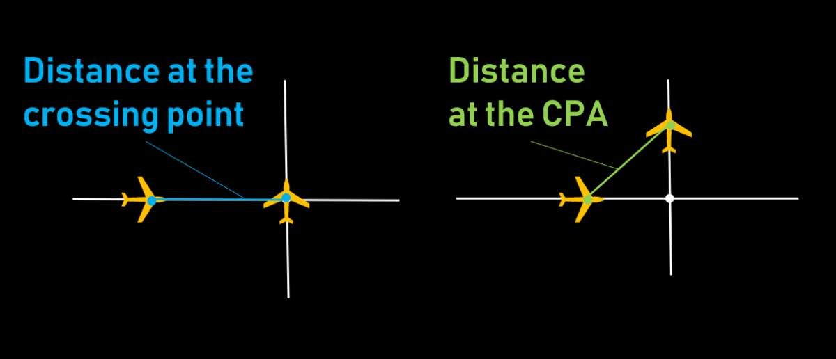
Speed Control
This article describes the use of speed control by air traffic controllers to manage the traffic flow and solve conflicts. It is focused on the en-route phase and describes the general provisions, typical uses and also gives some advice about the practical use of the method. Note that the advice is derived mostly from good practices and experience, and is in no way intended to replace or supersede local procedures and instructions.
Description
Speed control is used to facilitate a safe and orderly flow of traffic. This is achieved by instructions to adjust speed in a specified manner.
Speed adjustments should be limited to those necessary to establish and/or maintain a desired separation minimum or spacing. Instructions involving frequent changes of speed, including alternate speed increases and decreases, should be avoided. Aircraft should be advised when a speed control restriction is no longer required. The flight crew should inform ATC if unable to comply with a speed instruction.
The future position of an aircraft (and, consequently, separation) is determined by the ground speed. Since it is impractical to use it directly, the indicated airspeed (IAS) and Mach number are used instead to achieve the desired ground speed. At levels at or above FL 250, speed adjustments should be expressed in multiples of 0.01 Mach. At levels below FL 250, speed adjustments should be expressed in multiples of 10 kt based on IAS. It is the controller's task to calculate the necessary IAS or Mach number that would result in the appropriate ground speed. The following factors need to be taken into account:
- Aircraft type (range of appropriate speeds)
- Wind speed and direction (in case the two aircraft are not on the same flight path)
- Phase of flight (climb, cruise, descent)
- Aircraft level (especially if the two aircraft are at different levels)
Restrictions on the use of speed control:
- Speed control is not to be applied to aircraft in a holding pattern.
- Speed control should not be applied to aircraft after passing 4 NM from the threshold on final approach.
Phraseology
- Report indicated airspeed / report mach number / speed (in case the current speed cannot be obtained by other means, e.g. Mode S information)
- Maintain/increase/reduce [speed] [or greater/or less] [reason] [condition]. Examples:
- Maintain 300 knots or greater
- Maintain Mach .83 or less due converging traffic until [point name]
- Reduce speed 260 knots or less for sequencing
- Increase speed Mach .82 or greater for the next 10 minutes.
- Resume normal speed (cancels a previously imposed speed restriction)
- No *ATC* speed restrictions (cancels a previously imposed speed restriction)
- On conversion [speed]. This instruction is sometimes used for climbing or descending aircraft when the speed control includes the moment of swithcing between IAS and Mach number. Note: while this instruction is used in a number of countries, it is not part of the ICAO standard phraseology.
Typical Uses
- Separation adjustment (e.g. two successive aircraft are separated by 9 NM and the required separation over the FIR exit point is 10 NM)
- Separation preservation (e.g. two successive aircraft have the necessary separation but this may change if one of them or both change their speed)
- Delay absorption (an alternative to flying a holding pattern)
- Avoid or reduce vectoring:
- in some situations speed control may be used instead of vectoring
- in some situations speed control may be used in combination with a vectoring instruction, in order to reduce the time an aircraft flies on heading and/or the heading change.
Rules of Thumb
- Generally, 0.01 M equals 6 kt
- Speed difference of 6 kt gives 1 NM in 10 minutes
- Speed difference of 30 kt gives 1 NM per 2 minutes
- Speed difference of 60 kt gives 1 NM per minute
Benefits
- Speed control is often the most efficient way for solving conflicts and traffic sequencing.
- The added workload is relatively low, especially for thinner sectors where most level changes need to be coordinated with the neighbouring upper/lower sector.
Things to Consider
- Transition times should be taken into account. It usually takes a few minutes before the aircraft reaches the desired speed due to inertia.
- When an aircraft is heavily loaded and at a high level, its ability to change speed may be very limited.
- Aircraft experiencing turbulence often fly at reduced speed. Under such circumstances it is advisable to coordinate instructions for speed increase with the flight crew.
- Speed control needs more time to achieve the necessary separation compared to other methods (vectoring, level change, vertical speed control). For shorther ATS sectors (e.g. 10 minutes transit time) this method is effective for:
- Separation adjustment (e.g. if the aircraft already have some separation and need a few NM more, this could be achieved by speed control even in shorter ATS sectors)
- Preservation of achieved separation (e.g. if two successive aircraft of similar type already have the nevessary separation, an instruction to maintain the same speed would be appropriate)
- Impact of wind. Winds can make a slower aircraft (in terms of M or IAS) have higher groundspeed than a faster one. In a complex situation, it is usually better to use speed control for successive aircraft and other method (e.g. level change) for a converging conflict.

In this situation the three aircraft are of the same type and flying with the same Mach number. However, due to the strong winds, RAS365 is considerably faster. It is therefore advisable to use speed control for PRE078 (e.g. M078 or greater) and REK001 (e.g. M078 or less) and change the level of RAS365 (in this case, descend to FL330). - Maintaining the Mach number during climb (in unchanged wind) results in reduction of TAS (and therefore groundspeed). It is therefore possible that a succeeding aircraft catches up with the preceeding one even if the preceeding aircraft is assigned a higher speed.
- Maintaining IAS during descent (in unchanged wind) results in reduction of TAS (and therefore groundspeed). It is therefore possible that a succeeding aircraft catches up with the preceeding one even if the preceeding aircraft is assigned a higher speed.
- An instruction for speed reduction is generally incompatible with one for maintaining a high rate of descent. Such combinations are best avoided and should only be used after explicit coordination with the flight crew that the desired combination of lateral and vertical speeds is achievable.
- Speed reductions to less than 250 kt IAS for turbojet aircraft should be applied only after coordination with the flight crew.
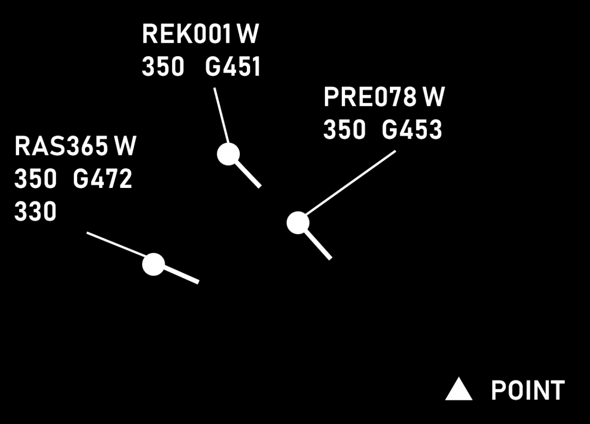
Source: www.skybrary.aero
Vertical Speed
This article describes the use of vertical speed (rates of climb and descend) by air traffic controllers to control the traffic flow and solve conflicts. It describes the general procedures, typical applications and associated risks. It also gives some advice on the use of this method by air traffic controllers. Note that any part of this article is not intended to act as or replace any existing local procedures.
Description
In order to facilitate a safe and orderly flow of traffic, aircraft may be instructed to adjust rate of climb or rate of descent. Vertical speed adjustments should be limited to those necessary to establish and/or maintain a desired separation minimum. Instructions involving frequent changes of climb/descent rates should be avoided.
Climbing/descending aircraft may be instructed to maintain a specified rate of climb/descend, a rate of climb/descent equal to or greater than a specified value or a rate of climb/descent equal to or less than a specified value.
An aircraft may be instructed to expedite climb or descent as appropriate to or through a specified level, or may be instructed to reduce its rate of climb or rate of descent.
Aircraft must be advised when a rate of climb/descent restriction is no longer required. The flight crew must inform the ATC unit concerned if unable, at any time, to comply with a specified rate of climb or descent.
Phraseology
The vertical speed clearance may be a part of a vertical clearance or a separate one. It specifies the required rate of climb/descent, usually in feet per minute and may also contain:
- upper or lower limit of the vertical speed, if applicable. The phrases "or greater" and "or less" are used in this case. If no limit is specified, then the aircraft is expected to maintain an exact vertical speed.
- a condition, if applicable (e.g. until passing a level or a point)
- further information (e.g. reason for the restriction, e.g. traffic, special use area, etc.)
PRE078 climb FL 370 at 1000 feet per minute or greater until passing FL 360 due crossing traffic.
Typical Uses
| Accomodation of climb requests |
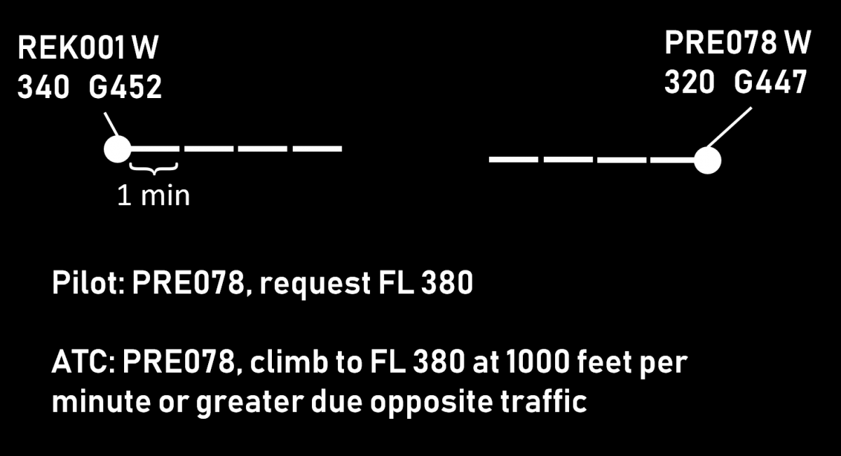 |
| Separation of departing and arriving traffic |
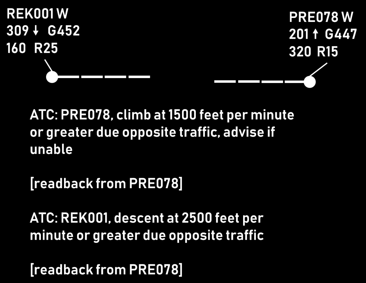 |
| Descending arriving aircraft below the overflying traffic | 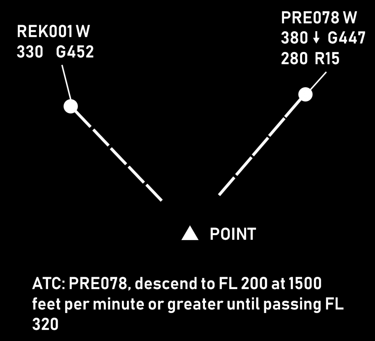 |
| Vertical sequencing, i.e. establishing and maintaining vertical separation between two (or more) climbing or two (or more) descending aircraft | 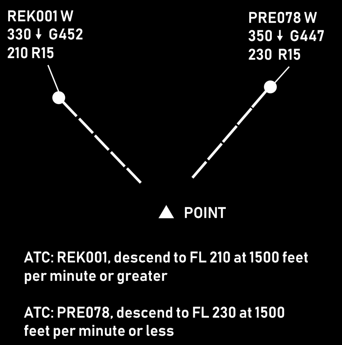 |
| Corrective action (e.g. when the unrestricted vertical speed is considered insufficient) | 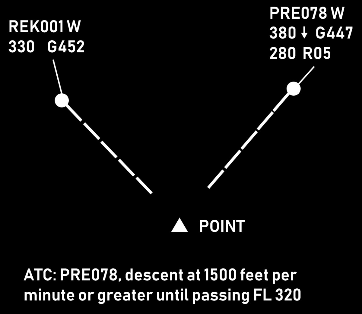 |
Benefits
When properly used, vertical speed control helps to achieve
- continuous climb/descend (fewer level offs), therefore better efficiency
- descents starting close to the top-of-descent
- timely accommodation of climb (mostly) and (sometimes) descent requests
- reduced workload due to reduced need for vectoring. A proper vertical speed ensures that horizontal separation will be preserved at least until vertical separation is achieved.
Associated Risks
- The margin for error is often reduced. This method relies mostly on maintaining vertical separation, which is much smaller than the horizontal one (e.g. 1000 ft as opposed to 5 NM). Therefore, any misunderstanding or non-compliance can easily result in loss of separation.
- Harder to monitor aircraft compliance (as opposed to e.g. vectoring). While the information for vertical speed is usually available, it may require some effort to present it. Furthermore, the interpretation of two (or more) numbers and the comparison of clearances versus performance takes more time than just having a look at the situational display (which is used to monitor horizontal separation).
- Aircraft may be unable to maintain the assigned rate of climb after certain level. If this happens, flight crew may or may not inform the controller.
- Wrong readback may easily ruin the plan (e.g. both aircraft descending with "or greater")
Things to Consider
- Rates of climb should be coordinated with the flight crew, especially:
- when approaching the cruising level
- when the climb is not desired by the flight crew
- when temperatures are high
- Some aircraft types are generally unable to maintain a high rate of climb (e.g. AIRBUS A-321, AIRBUS A-340-300)
- In order to mitigate the risks for crossing or opposite traffic situations, a safety buffer of 1 or 2 minutes should be used. This can be done by e.g.
- Issuing the clearance(s) a bit earlier
- Assigning vertical speeds that are a little higher (e.g. 1500 instead of 1000)
- High rates of descent are generally incompatible with low speeds. A combined instruction to reduce speed and increase the RoD should be coordinated with the flight crew.
- The aircraft needs time to achieve higher rates (2000 ft/min or higher). The transition period should be considered when calculating the necessary vertical speed.
- During the final 1000 ft, the vertical speed is usually 1000 ft/min or less. This is done to avoid level busts. It is therefore impractical to assign a rate of 2000 ft/min or greater if the aircraft is to climb or descend some 2000-3000 ft.
- The phrases "Expedite climb" and "Expedite descent", while being standard ICAO phraseology do not prescribe specific vertical speeds and should be used with caution. The general expectation in such case would be that:
- a climbing aircraft would climb at the highest rate possible (which may or may not be enough to achieve the desired result). It is therefore advisable that larger safety buffers are used or an alternative plan is ready for implementation.
- a descending aircraft would increase the rate of descent to at least 2000 ft/min. It is therefore advisable that this method is used for the first few thousand feet (e.g. for an aircraft at FL 390 "Descend FL 290, expedite passing FL 370 due crossing traffic")
- There should always be an alternative plan to accommodate for an aircraft being unable to continue climb with the desired rate.
Rules of Thumb
- Vertical speed of 2000 ft/min gives 10 FLs in 5 minutes
- Vertical speed of 2500 ft/min gives 10 FLs in 4 minutes
- Combined vertical speed of 4000 ft/min (e.g. RoD 2500 and RoC 1500) gives 20 FLs in 5 minutes
Combined vertical speed is the sum of the vertical speeds of a climbing and a descending aircraft, e.g. if aircraft A is climbing at 1500 ft/min and aircraft B is descending at 2000 ft/min, then the combined vertical speed is 3500 ft/min.
Source: www.skybrary.aero
Level Change
While there are various reasons for a level change, this article focuses on the conflict solving aspect.
Description
Changing an aircraft's level is often the easiest way for a controller to solve a conflict, i.e. a situation where two (or more) aircraft are expected to be closer than the prescribed separation minima.
Advantages:
- Comparatively smaller intervention. The aircraft continues to fly using own navigation (as opposed to vectoring) and follows the planned route (as opposed to proceeding direct to some distant waypoint).
- Faster to achieve. Even when the aircraft is to climb or descend by 2000 ft, only 1000 are often enough to ensure separation with the conflicting aircraft (see section Opposite Levels for details). This means that the conflict is usually solved within less than a minute.
- Easier to monitor on a situation display. Wind can influence both aircraft speed and flight direction. Additionally, speed vectors can change direction due to specifics of the surveillance system (especially the presence or absence of a tracker). On the other hand, all modern ATS systems provide an indication for climb or descend (an arrow next to the aircraft level). This makes it much easier for a controller to monitor aircraft compliance.
- Less controller workload. Changing an aircraft's level normally requires one instruction and about a minute to achieve the required separation. By contrast, speed control usually requires prolonged monitoring (the required separation "builds up" gradually). Vectoring requires more instructions - at least one for the heading change and one for the return to own navigation but more can be necessary depending on the circumstances. This will also require a longer period of monitoring.
Disadvantages:
- The main disadvantage of a level change is that aircraft normally fly at their optimal cruise levels. Therefore, any level change leads to reduced efficiency. This effect gets worse when increasing the difference between the desired and the cleared level.
- The use of temporary level change (i.e. the aircraft climbs/descends to a safe level to solve a crossing conflict and then returns to its cruising level) requires two vertical movements (one climb and one descend) which is also sub-optimal in terms of efficiency.
- There is an inherent risk of a blind spot, i.e. the controller may solve a medium term (e.g. 15 minutes ahead) conflict while at the same time create a new one with an aircraft just below or above the one being instructed to change level.
- When vertically split sectors are used, the level change may require coordination with an adjacent upper or lower sector which increases the workload for both controllers.
Climb Vs. Descent
After deciding to solve a conflict by a level change, the controller must choose between climb and descent. The former is generally preferred, as it leads to better flight efficiency. However, in some situations descent is the better (or the only) option, e.g.:
- The aircraft is unable to climb due to weight. Note that weight reduces as fuel is burnt so a higher level may be acceptable later. In this case the controller should take into account that the climb rate could be less than usual.
- The aircraft is approaching its top-of-descent. Instructing an aircraft to climb shortly before it would request descent is not very beneficial to flight efficiency and can increase controller workload (the higher the aircraft, the more potential for conflicts during the descent).
- Turbulence is reported at the higher level. Vectoring, direct route or speed control are generally preferable in this situation.
- The manoeuvre is to be performed quickly (e.g. due to a conflict being detected late). In this case, if a climb instruction is issued, it may be declined by the crew, thus losing precious time.
If the controller is in doubt as of which option is preferable (and if both are available), the controller may first ask the pilot (time and workload permitting). The fact that the range of available speeds is reduced at higher levels should also be considered. If the climb is to be combined with a speed restriction, this should be coordinated with the crew beforehand.
Opposite Levels
In many situations a level change would require the aircraft to climb or descend by 2000 feet (so that the new level is appropriate to the direction of the flight). However, sometimes it is better to use an opposite level, i.e. one that is only 1000 feet above/below. This is often a good solution in case of crossing conflicts, i.e. where the paths of the two aircraft only intersect at one point and the level change is expected to be temporary.
- The solution is better in terms of flight efficiency because the aircraft will fly as close as possible to the desired level and the need for vertical movement will be reduced
- The opposite level may happen to be within the own sector, therefore no coordination with an adjacent upper or lower sector would be necessary. This reduces the workload of both controllers and is especially useful when there are multiple, vertically-split sectors.
It should be noted, that a few risks exist with this solution:
- If there is a flight on an opposite track, the normally expected 1000 ft separation would not exist
- In case of radio communication failure, the aircraft may fly at an opposite level much longer than expected and the exact moment of returning to the previous level may not be easy to determine.
The picture below show a situation where the use of opposite level is preferable. The level change will be required for a few minutes only and there is no opposite traffic.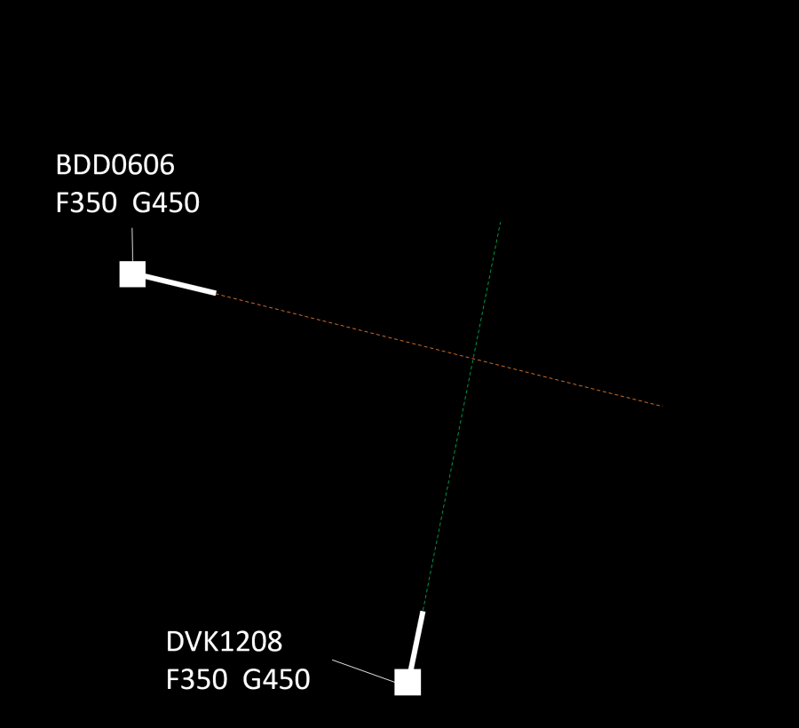
The picture below show a situation where the use of opposite level is not feasible because of opposite traffic. Therefore, a level change of 2000 ft is preferable.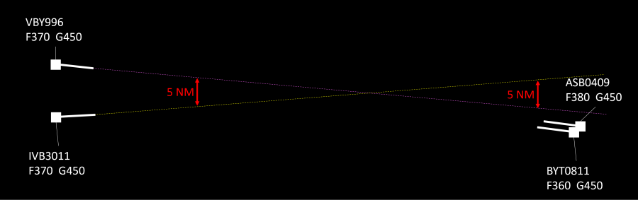
The use of opposite levels can sometimes be justified when the conflict is at the sector exit point. This solution, however, is subject to approval from the downstream controller. The feasibility of this option depends on the geometry of the conflict (are the aircraft diverging after the point of conflict) and on the traffic situation (are there aircraft that are flying at the same level on an opposite track).
Priorities
As a general rule, when two aircraft are at the same cruising level, the preceding aircraft would have priority, i.e. the succeeding aircraft will have to climb or descend. Other criteria may be specified in the manual of operations or other documents containing local procedures. In any case, the controller may deviate from these procedures based on the traffic situation. For example, if changing the level of the succeeding aircraft would create a new conflict (and thus, a new intervention would be necessary), the controller may opt to work with the preceding aircraft. Naturally, flights in distress, or those performing SAR operations, would have priority over other traffic. This includes obtaining (or maintaining) the desired level while a lower priority traffic (e.g. a commercial or general aviation flight) would have to change level. Other priorities may be specified in local procedures (e.g. flights with head of state on board).
Vertical Speed Considerations
Normally, vertical speed is not considered an issue in case of a level change solution to a conflict. This is because in most cases the instruction is issued well in advance (5-15 minutes before the potential separation breach) and the level change is 1000 or 2000 ft, which means that vertical separation will be achieved comfortably prior to losing the required horizontal spacing. Nevertheless, there are some situations where it might be necessary to ensure that the vertical speed will be sufficient. These include:
- There is a reason to believe that the aircraft will not (be able to) climb fast, e.g. a heavy long-haul flight in the initial cruise stage, the aircraft type is known to climb slower than others, the new level is near the ceiling, etc. While 1000 ft/min means that 1000 ft separation will be achieved in one minute, if the rate drops to 200 ft/min, the required time will be 5 minutes. In the scenario where 2000 ft level change is necessary (e.g. converging traffic at the sector exit point and an opposite traffic 1000 ft above), a 200-300 ft/min climb rate will result in a 7-10 minute climb.
- Sometimes, if a descent rate is not specified, the manoeuvre may start at rates in the range of 500 ft/min. In this case, a 2000 ft level change will require 4 minutes as opposed to only 1 or 2 if "normal" vertical speeds of 1000-2000 ft/min are used.
In such situations the controller should either:
- ensure the vertical speed will be sufficient (e.g. by specifying a desired rate of climb or descent), or
- issued the instruction early enough, or
- if the above are not possible, an use an alternative solution.
Source: www.skybrary.aero
Runway Change Guide
Runway changes might be tricky, especially during phases with a lot of traffic. This guide should help you to manage this situation. Example of a runway change at Frankfurt/Main EDDF from 07 ops to 25 ops.
When is a runway change initiated?
For this, a look at the METAR and the TAF is useful. Basically, runway 25 is preferred in case of a definite 25-wind (between 160 and 340 degrees) or variable wind (according to the regulations, up to a tailwind component of 5 knots, although it does not depend on one knot). In many cases, 07 is still used with constant weak 07 wind, e.g. 030/5, although the tailwind component on 25 is therefore less than 5 knots. The reason for this are smaller gusts, which are briefly larger than 5 knots, but are not displayed in the METAR).
In case of doubt, a look at FR24 helps, which configuration is operated in real. However, in individual cases, there may be other reasons for a runway change in real (police helicopter mission, failure of navigation equipment, etc.).
Who decides, when a runway change is initiated?
The tower supervisor/coordinator decides to rotate, but Approach is involved in deciding exactly when to rotate (see below).
How does the Runway Change work once the decision has been made?
Tower calls Approach and informs about the upcoming runway change. In addition, the center controllers or, if available, a center supervisor should be informed so that other STARs can be cleared if necessary. Depending on the traffic situation, Approach then decides who will be the last inbound for 07L and 07R respectively.
Apart from inbound rushes, it is usually quite simple: those who are already more or less across the field still get 07 in any case, while those who have just flown into the TMA are cleared for 25. Approach can either assign vectors or change the STAR for the pilot, depending on personal preference.
In the inbound rush, however, Approach should try to find a suitable gap where there are not so many inbounds for a few minutes. If the wind is acceptable, the runway change can be postponed a bit if the inbound situation does not improve in the next few minutes. Nevertheless, after 20 minutes at the latest, a decision should be made as to who will be the last inbounds for 07L and 07R.
In the optimum case, these are two aircraft that land at approximately the same time. The call signs of these two aircraft are then passed on to the tower as well as an approximate landing time.
"DLH123 last for 07L, DLH456 last for 07R, both landing in about 15 minutes".
If the tower knows this, it must then be considered for all outbounds whether they must be cleared for 25, or whether they can still depart from 07. This consideration is primarily the task of the tower supervisor/coordinator. What must be avoided is that another outbound takes off from 07 even though the first planes are already on the 10-mile final approach of 25. Of course, the pilots should also be given a reason for the reclearance.
"We are changing runway direction, therefore you will be recleared, are you ready to copy?...".
If, as in the example above, the last aircraft lands on 07 in 15 minutes, the tower can still allow take-offs from 07 for another 10 minutes. Based on the taxiing time, it is, therefore, necessary to estimate who will still get the 07. If in doubt, calculate conservatively and reclear too early rather than too late.
Aircraft that are with apron control and are to be recleared must be sent back to Delivery since apron control is not allowed to issue route clearances. Delivery will contact Apron and ask them to send aircraft XY to Delivery for a reclearance. Outbounds, which are already at the tower frequency, may of course also be cleared by the tower.
As soon as the aircraft are recleared, taxi instructions to holding point runway 25 are issued. Ideally, the aircraft will reach the holding point 25 when the last inbound 07 has just landed. However, a few minutes delay at the holding point is not a problem in such a situation.
Exceptions: SULUS is cleared to 18 and KOMIB does not exist at 25, instead CINDY must be filed.
As soon as the last inbound for 07 is safely on the ground, the tower should inform Approach directly and, to be on the safe side, ask for a release for the first 25 departure.
Approach, conversely, must time the inbounds so that the first 25-inbound is approximately on the 10-mile final approach when the last 07-inbound is just touching down. In case of a missed approach at the last second, this gives enough room to turn away.
If there is a lot of traffic, the downwind and final will automatically be very long. If necessary, aircraft will have to enter a holding for a short time, but this is usually not necessary, since the runway change should be timed as described above so that there is not so much traffic. Within the TMA, Approach can also get creative, e.g. with three-sixties, so that the downwind does not become too long.
As with everything, it is important that the individual ATC stations communicate and coordinate so that everyone is fully aware of each other's traffic and plans.
Summary
- The decision is based on the METAR and TAF
- The decision is made by the tower supervisor/coordinator, but approach is also involved in the decision
- Approach decides the last arrivals for 07L and 07R
- Tower can issue the last takeoff clearances for 07 until approximately 5 minutes before the last inbounds
- The first inbound for 25 can be on a 10-mile final approach when the last 07-inbound is just touching down
- The first 25 departure should be released by Approach
Emergencies - Controller Guide
An emergency is, by definition, an emergency involving an aircraft in the air that poses a serious and immediate threat for the aircraft and/or its occupants.
The handling of each emergency for the controller is highly individual, as no two situations are the same. This guide should therefore be seen as a basis / orientation.
Relevance to Vatsim
According to the VATSIM Code of Conduct, a pilot may only declare an emergency when they receive ATC service. The controller may request the pilot to terminate the emergency at any time and without giving reasons. The pilot must comply with this request immediately or disconnect from the network.
Furthermore, no hijacking may be simulated and the transponder code 7500 may not be set.
For you as an ATCO this means: If you are not familiar with handling an emergency, rather refuse it. If you are currently too busy (e.g. due to a high traffic load), or are in doubt for any other reason, it is reasonable to refuse the emergency. Neither the pilot nor you will benefit in any way if the emergency is handled unsafely, completely unrealistically or carelessly.
Types of emergencies
On the pilot's side, there is a difference between the two well-known messages "Mayday" and "Pan Pan":
-
A "Mayday" is the notification of an emergency in which there is a serious or imminent danger and immediate assistance is required.
-
A "pan pan" is an emergency message in which a safety-relevant situation exists, but does not require immediate assistance.
On the controller side, the term emergency is defined much more broadly. A distinction is often made between a local standby, a full emergency and an aircraft accident, although not all types of emergency fit into one of these categories.
- A local standby is an aircraft that is known or suspected to have a malfunction which under normal circumstances does not prevent the aircraft from landing safely. Pilots often do not report a "pan pan" or a "mayday", but the flight is still considered an emergency by air traffic control. Certain measures are initiated which can only be simulated on Vatsim (e.g. calling out the fire department)
Examples of a local standby are
-
Engine problems (e.g. strong vibrations, single engine failure)
-
Hydraulic problems (e.g. flaps cannot be extended)
-
Landing gear problems (e.g. nose wheel steering has failed)
-
Smoke / odor in the cockpit or cabin
-
Problems with cabin pressurization (e.g. broken windscreen)
-
Structural problems (e.g. after a bird strike)
-
-
A full emergency is an aircraft that is known or suspected to be in an emergency that results in a risk of an accident. The differentiation between local standby is sometimes blurred.
Examples of a full emergency are
-
Aircraft fire / engine fire
-
Landing gear cannot be extended
-
- An Aircraft Accident is an accident involving an aircraft that is at the airport or in the immediate vicinity of the airport.
- Other emergencies that are not of a technical nature and therefore cannot be classified in any of the categories are, for example:
-
VFR with loss of orientation
-
VFR in IMC
-
Medical emergency in the aircraft
-
Radio failure
-
Handling of an emergency
As every emergency is different, there is no one-size-fits-all guide for handling emergencies. Nevertheless, there is a scheme that can help you as a controller to handle an emergency in a structured way in a stressful situation. This scheme is known as the ASSIST scheme, where each letter stands for a measure:
- Acknowledge: The first thing to do is to recognize an emergency as such. The controller should therefore acknowledge "Mayday" and "Panpan" messages and also ensure that the nature of the emergency and any details have been understood correctly.
- Separate: The surrounding airspace should be cleared to a greater or lesser extent depending on the emergency. This includes increasing the separation to the emergency aircraft by the center and approach controllers, as the cockpit crew is very busy or very stressed during an emergency and might implement ATC instructions late or incorrectly. On approach, the runway should be cleared as early as possible so that no "tight" maneuvers have to be performed with the aircraft concerned. If necessary, other approaches may be instructed to go around and VFR aircraft may be requested to leave the control zone.
- Support: The pilot should be supported as much as possible. However, the pilot should not be distracted with unnecessary radio messages. Among others, the following support options are available:
- Ask about general support / intentions
- Suggest nearby / suitable airports
- List / suggest approach types (depending on the weather, visual approaches may also be an option)
- If there are several runways, suggest suitable runways (e.g. the longest / widest runway)
- Clarify whether the pilot can leave the runway after landing and / or taxi normally
- Simple instructions - radio messages should not contain more than one or two pieces of information
- Inform: Other ATC stations affected by the emergency should be informed. For example, the center forwards the emergency to the approach, the approach to the tower and the tower to the ground. In this "game of telephone", particular care should be taken to pass on information correctly.
- Silence: Depending on the situation and traffic load, radio silence can be imposed on the frequency. The phraseology here is in accordance with AIP GEN 3.4:
- "All stations, stop transmitting, MAYDAY"
- The following phraseology is used to cancel radio silence: "All stations, distress traffic ended"
- Time: The pilot should never be stressed by the controller. They should be given sufficient time to solve their problem. Sometimes it can take several minutes to make a decision and work through the relevant checklists.
Identification
Unlike tower controllers, radar controllers cannot look out of the window to provide air traffic services. They have to rely on data collected by so-called surveillance systems. Examples of these systems are primary surveillance radar (PSR) and secondary surveillance radar (SSR).
Primary surveillance radar (PSR)
When radar was invented, it only existed as a primary radar. A primary radar emits electromagnetic waves in all directions and displays a dot on the screen for each reflection detected. However, there is no way to tell which dot on the screen belongs to which aircraft - this is where identification comes into play.
An aircraft is identified when we see its target on the radar screen and are sure which aircraft it belongs to.
But how can we know which target is which aircraft if it is not transmitting data?
When using PSR, there are several so-called identification methods [1]:
-
Position reports: correlating a target with an aircraft reporting its position above or its distance and bearing from a significant point on the screen, and ensuring that the target's track matches the path/reported heading of the aircraft.
-
Departing aircraft: Assignment of a target to a departing aircraft within 1 NM of the end of the runway.
-
"Turn" method: Instruction to an aircraft to change course by 30 degrees or more and observation of this change.
-
Transfer of identification: The identification for an aircraft can be transferred to you by another controller who has identified it.
Secondary surveillance radar (SSR)
Modern surveillance systems use a transmitter-receiver combination that interrogates transponders on board the aircraft, which then transmit data back to the ground station. This is the fundamental difference to PSR systems, where the ground station receives passive signals (reflections). There are different interrogation modes that transmit different data [2]:
| Mode |
Transported data |
| A |
4-digit octal identification code, e.g. squawk |
| C |
Aircraft's pressure altitude |
| S |
Callsign, unique 24-bit address, selected altitude, speed over ground, indicated airspeed, etc. [3] |
Modes A and C are often combined into mode 3 A/C. When using SSR, there are additional methods of identification:
-
Recognition of the aircraft identifier on the label,
-
Recognition of an assigned discrete code whose setting has been confirmed by the pilot,
-
Observation of the setting/change of an instructed individual code,
-
Observation of compliance with a squawk IDENT instruction
-
Transfer of identification: The identification for an aircraft can be transferred to you by another controller, who in turn has identified the aircraft.
The most common method of identifying an aircraft in our simulated environment is "recognizing the aircraft ID (call sign) in an SSR label". When you see a label with a callsign, that callsign is associated with a flight plan and the aircraft is correctly identified. If a pilot is unable to switch on their transponder, you can identify them using the methods listed for the primary radar.
This means that in the environment of Vatsim Germany (and with the standard ES packages) we can consider almost any aircraft as identified.
Before providing air traffic control services (any service provided directly using an ATS surveillance system, e.g. primary or secondary radar), the controller must identify the aircraft concerned and inform its pilot.
The information to the pilot about the identification may be omitted if the pilot was already identified by the previous sector.
Reading and Deviation of Transponder Values
This topic is less relevant on VATSIM than in real life. In reality, there are various rules that define when a flight level is considered "reached," "maintained," or "left." For VATSIM, however, it is generally sufficient to assume a tolerance of 200 feet. It is important to note that this should not be exploited to justify breaches of separation. In any case, pilots should be addressed about deviations (and, for example, asked to correct their altimeter settings).
[1] ICAO Doc 4444, Procedures for air navigation services - Air traffic management, Sixteenth edition, 2016
[2] Aviation transponder interrogation modes, Wikipedia
[3] Skybrary Mode S