| **Sector** | **Station ID** | **Login** | **Frequency** | **Remark** |
| **Pickup | ||||
| **Arrival North** | DFAN | EDDF\_N\_APP | 120.805 | primary |
| **Arrival South** | DFAS | EDDF\_S\_APP | 125.355 | -- |
| **Feeder | ||||
| **Director North** | DFFN | EDDF\_H\_APP | 127.280 | secondary |
| **Director South** | DFFS | EDDF\_L\_APP | 118.505 | -- |
| **Departure** | ||||
| **Departure North** | DFDN | EDDF\_N\_DEP | 120.155 | -- |
| **Departure South** | DFDS | EDDF\_S\_DEP | 136.130 | -- |
All APP/DEP frequencies shall always be cross-coupled by the responsible controller.
### Terminal Maneuvering Area (TMA) Below you can find the arrival sector of Frankfurt with its subsectors. In case there is only one controller online, the whole sector is controlled by them. All subsectors combined constitute the Terminal Maneuvering Area (TMA). The MVA chart is available via [chartforx.org](https://chartfox.org/eddf "chartfox.org") or as Topsky Map at Euroscope. The airspace structure can be found at [openflightmaps.org](https://www.openflightmaps.org/ "openflightmaps.org").| [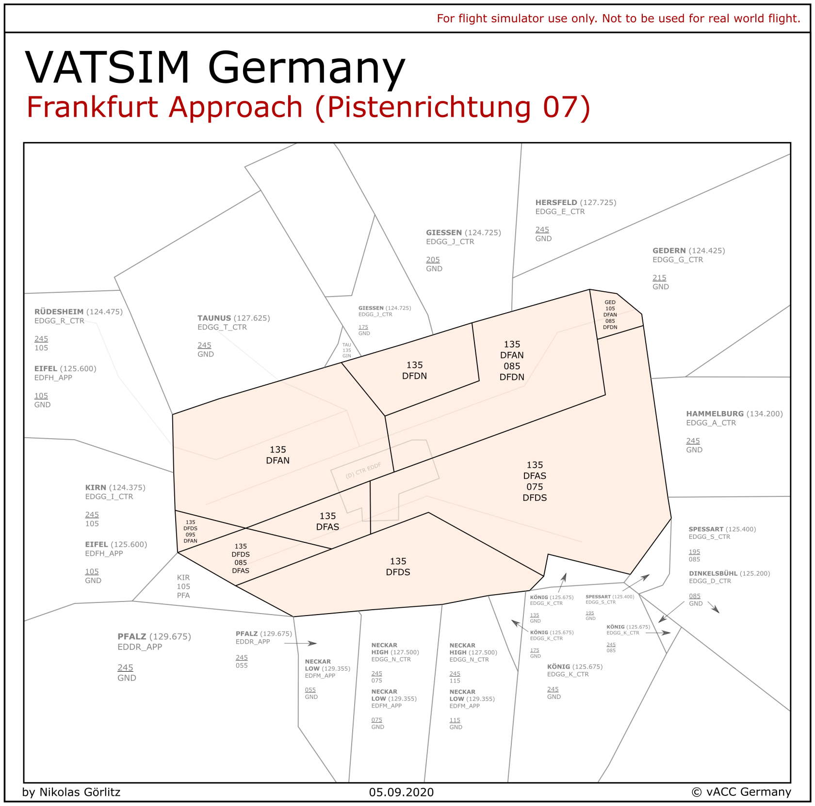](https://knowledgebase.vatsim-germany.org/uploads/images/gallery/2022-11/frankfurt-approach-sectors-07-config.png) | [](https://knowledgebase.vatsim-germany.org/uploads/images/gallery/2022-11/frankfurt-approach-sectors-25-config.png) |
| **Runway** | **STAR** | **Routing** | **Old Transition** |
| **25** | A | North | 25N-Transition |
| B | South | 25S-Transition | |
| **07** | C | South | 07S-Transition |
| D | North | 07N-Transition |
| **Runway** | **STAR** | **Routing** | **IAF** |
| **25 | G | North | ORVIV |
| South | KUGUK | ||
| **07 | R | North | IBLUS |
| South | ULNOK |
Even after the clearance for the STAR, the Arrival controller can always use vectors for sequencing.
**Releases:** Traffic handed over from Center to Frankfurt Arrival is fully released for turns and further descent. Arrival needs to ensure sufficient spacing between traffic. Inbounds should always stay clear of the departure sector even if Arrival handles departures as well. #### Approaches The following approaches are available at Frankfurt.| **Approach** | **Runways** | **Remarks** |
| **ILS** | 07R/25L | 3° glide path *RNAV required* |
| **ILS X** | 07C/25C | 3° glide path *non-RNAV* |
| **ILS Y** | 07L/25R | 3.2° glide path *RNAV required* |
| **ILS Z** | 07L/25R 07C/25C | 3° glide path *RNAV required* |
| **GLS Y** | all | 3.2° glide path *shall only be used upon pilot request* |
| **GLS Z** | all | 3° glide path *shall only be used upon pilot request* |
| **RNP X** | 07L/25R 07C/25C | noise abatement procedure *(former RNP Y)* |
| **RNP Y** | all | 3.2° glide path |
| **RNP Z** | all | 3° glide path |
**Targetspacing** for inbounds only need to be applied by Arrival when **requested by Tower!** Otherwise radar or WTC seperation is used by default.
These target spacings at handoff are as follows: - **07R arrivals:** 5 NM (minimum 4 NM at touchdown) - **07L arrivals:** Radar Separation - **25L arrivals:** 6 NM (minimum 5 NM at touchdown) - **25R arrivals:** 5 NMWake Turbulence Separation must be applied where necessary all the time.
#### Separation on final As per the AIP for EDDF, separation between two aircraft approaching the same runway can be reduced to 2.5 NM under some conditions: > **4. Reduced minimum radar separation between approaches to runways 07L, 07C, 07R, 25R, 25C and 25L** > > 4.1 During approaches to runways 07L, 07C, 07R, 25R, 25C and 25L, the radar separation minimum of 2.5 NM applies on final approach between 10 NM and touchdown, provided the following conditions are met: > > 1. The preceding aircraft has the same or a lower weight category. Aircraft of the weight category SUPER, HEAVY and the B757 as preceding aircraft, are excluded from this procedure. > 2. The exit taxiways of the runway can be observed from the control tower visually or by means of surface movement radar. > 3. The runway is dry. > > 4.2 The reduced radar separation minima may also be applied between staggered approaches to the parallel runways. In these cases, neither the line of sight of the exit taxiways (4.1 b) nor the runway conditions (4.1 c) need to be considered as a precondition. Additionally, the separation between dependent parallel approaches to the parallel runway systems 25L/25R and 07L/07R can be reduced to 1.5 NM.It is very important not to drain out the final. Even if the Approach sector is too busy and traffic management holdings are necessary, usually there is no need to completely close sector entry for more than 5 minutes (around one orbit in the hold). After a short closure because of an overload on the Arrival/Director stations, it is recommended to set an aircraft rate per time, e.g. not more than one aircraft per 4 minutes via RASVO/IMCOM/ROLIS/KERAX and not more than one aircraft per 3 minutes via SPESA. Try to clear the holdings as quickly as possible. Due to the enormous capacity in parallel operations (up to 60 movements per hour), usually extensive holding usage is not necessary.
Besides the traditional holdings radar vectors along the downwind and final (without an approach clearance) can be used to delay inbounds as well. In this way, there is a lot of capacity to hold aircraft and it is easy to dissolve. It is recommended to use this procedure when the airport is completely closed for a short time. Do not have too many aircraft in this holding structure to make separation easy – the Center holdings can be used for any additional aircraft. ### Departure Procedures Inbounds should stay above outbounds, clear of the Departure sector (at or above FL90). Outbound should stay at FL80 or below until they are clear of inbound traffic. If Departure and Arrival are staffed, a direct climb to FL110/FL130 can be coordinated if there is no conflict. If the Arrival controller takes over the respective Departure sector, it is possible to let a departure climb above an arriving aircraft if the climb rate permits. Therefore make sure that at first inbound and outbound are vertically separated. Only when it is predictable that the outbound can overclimb the inbound, further climb should be issued. Departing aircraft shall be handed over to the appropriate Center controller on the following flight levels to the following station:| **Level** | **SID / Waypoint** |
| FL110 | CINDY / SULUS (out of RWY 18) |
| FL130 | ANEKI / SOBRA / ULKIG / OBOKA / MARUN / TOBAK / SULUS (out of 07) |
Dependent operations are much easier to use but it does not have as much traffic capacity as parallel operations do. Usually, dependent operations are used on VATSIM. Especially during bigger events parallel operations may be the best way of handling the traffic.
#### Parallel Independent Operations Arriving aircraft on runway 07L/25R are independent of arriving aircraft on runway 07R/25L as soon as they are established on the localizer. 1. The first Arrival controller to be contacted (not Director!) by the pilot assigns the runway. After the runway assignment, the handoff from one Arrival controller to another Arrival controller is necessary if the aircraft leaves one Arrival sector and enters another Arrival sector. 2. The pilot is handed over from the appropriate Arrival controller to the appropriate Director controller (Director North for all runway 07L/25R arrivals, Director South for all runway 07R/25L arrivals) no later than 10 NM before the expected turn onto the final (earlier handoff preferred). 3. Before hand-over from the Arrival to the Director controller, the aircraft must be instructed to descend to the intercept altitude (5000ft for 07L/25R, 4000ft for 07R/25L) whenever possible (this is strongly preferred!). If this is not possible, FL60/6000ft or higher could be used. Often it makes sense to instruct all pilots to maintain 220 KIAS before the handover to the Director controller. 4. The localizer or ILS clearance cannot be issued before the aircraft has reached the ILS intercept altitude. 5. Aircraft have to be at intercept altitudes inside the turn areas (see image). Any aircraft in the turn area not at intercept altitude has to be coordinated with both directors. If an aircraft is flying straight in and can not reach intercept altitude before entering the turn area, it has to be turned towards the downwind. 6. Outbound capacities can be reduced due to parallel operations. Target spacings (see above) should still be met wherever practicable.With two Feeders it might be helpful to have all arrivals for runway 25L/07R (e.g. the ones not allowed on 25R/07L) on the southern downwind by clearing also arrivals from the north for the southern STAR. Inbounds from the north downwind for the southern runway will be handed over to FFS.
##### Procedures for parallel independent - During this mode of operation, aircraft have to be able to fly 1 NM straight and level before intercepting the LOC and 2 NM straight and level before intercepting the GS (See ICAO DOC 4444). - The Non-Transgression-Zone (NTZ) provided with the local Euroscope files defines a zone that must not be violated by approaching traffic. According to the ICAO definition, upon violation of the NTZ by one of the approaching aircraft, the aircraft in the adjacent approach must be instructed to perform a Go Around. It is not sufficient to instruct a Go Around for the aircraft violating the NTZ. - The intercept of aircraft has to be performed so, that the aircraft establishes on the LOC inside the turn area. - The line left of the turn area indicates the latest point at which an aircraft has to be established on the LOC, not below the published ILS intercept altitude, due to noise abatement reasons. Intercepts closer to the airport should be the exception if for example pilots overshoot the LOC and have to be turned back toward the ILS. [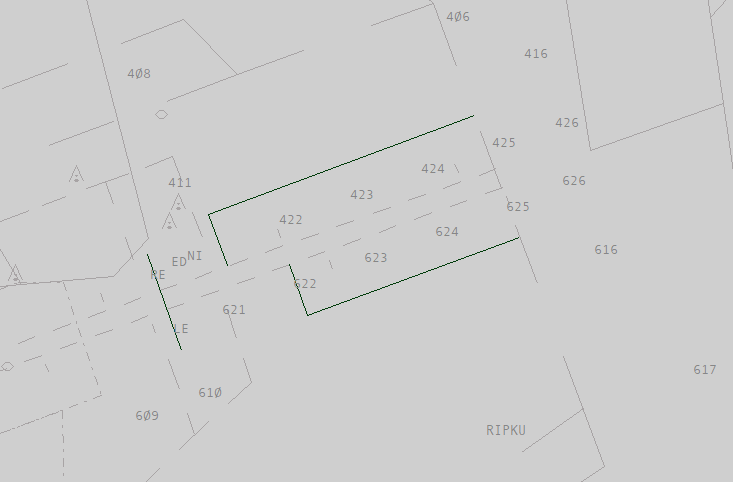](https://knowledgebase.vatsim-germany.org/uploads/images/gallery/2022-07/eddf-turn-areas-25.png)*Turn areas for 25 configuration (green)* ##### Staffing Possible staffing configurations (no others are possible!): 1. **DFDN, DFAN, DFFN** (recommended if no more controllers are available but there is too much traffic for staggered operations. Otherwise use staffing option 2 or use staggered operations.) 2. **DFAN, DFAS, DFFN, DFFS** (DFDN, DFDS) (recommended!) 3. **DFAN, DFAS, DFFN** (DFDN, DFDS) (not recommended!) 4. **DFAN, DFFN, DFFS** (DFDN, DFDS) (usually not recommended!) 5. **DFAN, DFFN** (only in exceptional cases where there aren't more controllers but the traffic amount does not allow staggered operations. This should be changed back to staggered operations as soon as practical.) *Station in brackets: additionally one or more of these stations can be staffed.* If just one Director is staffed, he takes over the other Director. DFAS and DFAN, DFFN and DFFS as well as DFDN and DFDS can be interchanged if one of the frequencies is preferred due to the neighbor station.In real life parallel operations can only be used with two Director controllers. On VATSIM parallel operations with only one director is possible if necessary, but not recommended. With two directors, only parallel operations are possible.
#### Dependent Operations Arriving aircraft on runway 07L/25R are dependent to arriving traffic on runway 07R/25L. However, the separation for aircraft established on the parallel runways can be reduced to 1.5 NM. Wake turbulence separation has to be given at any time for aircraft approaching the same runway. It is also important that all aircraft have to fly a precision approach. If an aircraft is unable for a precision approach, it is required to switch to alternating operations for this aircraft. ##### Procedures Director assigns the runway on the initial contact or very soon thereafter. The handoff from Arrival to Director should take place no later than 10 NM before the expected turn onto the final (earlier handoff is preferred when able). ##### Staffing Possible staffing configurations (no others are possible!): 1. **FAN** (FFN, FDN, FDS) 2. **FAN, FAS, FFN** (FDN, FDS) (not recommended!) Station in brackets: additionally one or more of these stations can be staffed. FAS and FAN, FFN and FFS as well as FDN and FDS can be interchanged. #### Alternating Operations All arriving aircraft must maintain radar separation. Reduced Minimum Radar Separation (RRS) can be applied if necessary. ##### Procedures Director assigns the runway on the initial contact or very soon thereafter. The handoff from Arrival to Director should take place no later than 10 NM before the expected turn onto the final (earlier handoff is preferred when able). ##### Staffing Possible staffing configurations (no others are possible!): 1. **FAN** (FFN, FDN, FDS) 2. **FAN, FAS, FFN** (FDN, FDS) (not recommended!) Station in brackets: additionally one or more of these stations can be staffed. FAS and FAN, FFN and FFS as well as FDN and FDS can be interchanged. ### Minor Airports within the TMA #### Egelsbach Egelsbach (EDFE) is an uncontrolled airfield within the Frankfurt TMA. Egelsbach is handled the same way as any other uncontrolled airfield. If Egelsbach Radio is offline, it can be handled by DFAS if this controller has the VATSIM AFIS endorsement. Egelsbach airport can be delegated to Frankfurt Tower if this controller has the AFIS endorsement. If no controllers have the AFIS endorsement, Egelsbach airport cannot be covered with AFIS service. Although Egelsbach is an uncontrolled airfield, a big ratio of the traffic is business traffic. This traffic is usually IFR but must depart or land VFR in Egelsbach. Standard procedures for IFR pickup or IFR cancellation apply. It is recommended to execute IFR cancellations southeast of EDDF at 4000ft or below. It is also recommended to instruct pilots inbound Egelsbach to leave airspace CHARLIE to below as soon as IFR is canceled. Charts are available in the [AIP VFR](https://aip.dfs.de/BasicVFR/pages/C019C6.html "DFS AIP VFR EDFE"). #### Wiesbaden IFR in-/outbounds to Wiesbaden (ETOU) need to be separated to Frankfurt in-/outbounds. Coordination between Arrival and Frankfurt Tower might be necessary. An ILS approach is only available for runway 25 while both runways have RNP and TACAN approaches. Wiesbaden's extended Northern pattern enters airspace D above the Wiesbaden CTR up to 2100ft. If use of the extended pattern is required, Wiesbaden Tower will request approval from DFAN. IFR departures out of Wiesbaden are initially cleared to the final waypoint of the SID by Wiesbaden Ground. Further clearance to the destination is required once the aircraft is handed off to Langen Radar. > **DUKE31**: Langen Radar, Duke 31, 2300ft, climbing 5000ft. **Langen Radar**: Duke 31, Langen Radar, identified, climb to FL130, cleared to Stuttgart via flight planned route. > **DUKE31**: Duke 31, climbing FL130, cleared to Stuttgart via flight planned route. Charts are available via [MILAIS GEMIL FLIP US DoD](https://www.milais.org/publications.php "MILAIS Publications"). Wiesbaden arrivals sometimes need to be descended earlier than Frankfurt arrivals to ensure a manageable descent profile. The following table shows some **tips on how to achieve this**.| **Runway** | **Direction** | **Routing and descent profile** |
| **07** (RNP) | from the Northwest | direct to OU452 to cross OU452 at 5000ft, from OU452 cleared for the approach |
| from the Northeast | direct to OU455 to cross OU455 between 5000ft and 7000ft, from OU455 cleared for the approach | |
| from the South | ||
| **25** (ILS) | from the Northwest | direct to TAU to cross TAU between 5000ft and 8000ft, from TAU cleared for the approach |
| from the Northeast | direct to OU117 to cross OU117 between 4000ft and 7000ft, from OU117 cleared for the approach | |
| from the South | direct OU115 to cross OU115 at 4000ft, from OU115 cleared for the approach |