Approach
Arrival can be split in 6 stations as shown in the table below.
| Sector | Station ID | Login | Frequency | Remark |
| Pickup |
||||
| Arrival North | FAN | EDDF_N_APP | 120.800 | primary |
| Arrival South | FAS | EDDF_S_APP | 125.350 | -- |
| Feeder |
||||
| Director North | FFN | EDDF_H_APP | 127.275 | secondary |
| Director South | FFS | EDDF_L_APP | 118.500 | -- |
| Departure |
||||
| Departure North | FDN | EDDF_N_DEP | 120.150 | -- |
| Departure South | FDS | EDDF_S_DEP | 136.125 | -- |
All APP/DEP frequencies shall always be cross-coupled by the responsible controller.
Terminal Maneuvering Area (TMA)
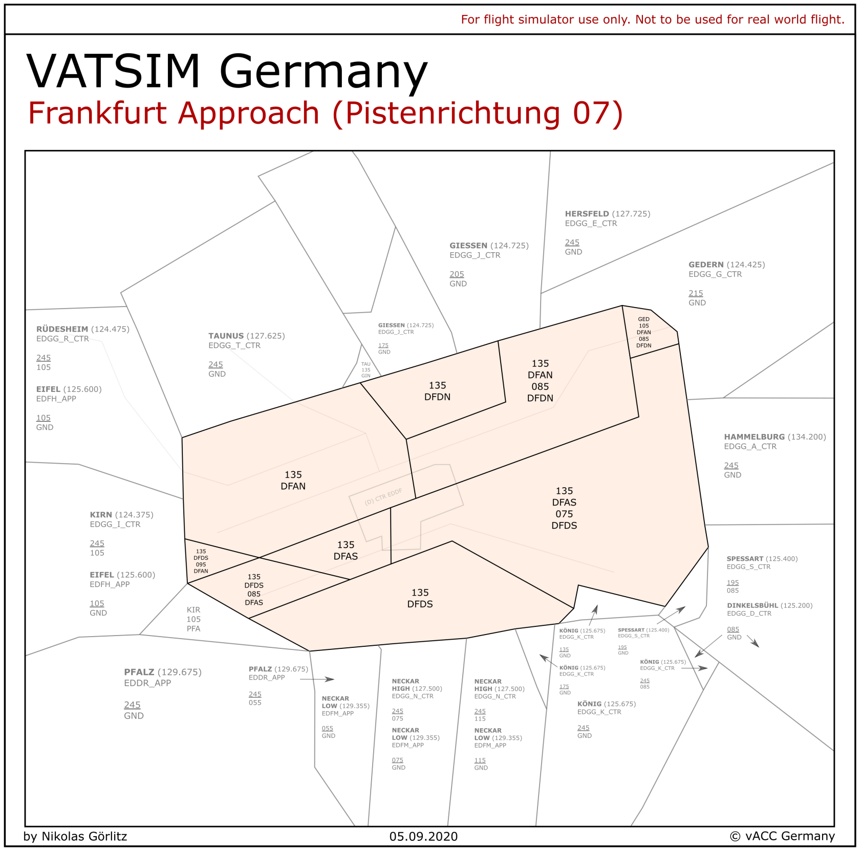
At the right you can find the arrival sector of Frankfurt with its subsectors. In case there is only one controller online, the whole sector is controlled by them. All subsectors combined constitute the Terminal Maneuvering Area (TMA). The MVA chart is available via chartforx.org or as Topsky Map at Euroscope. The airspace structure can be found at openflightmaps.org.
 |
 |
Departure: If only one Departure controller is online, he takes over the other Departure sector. If no Departure controller is online, Arrival North takes over Departure North and Arrival South takes over Departure South. If only one Arrival controller is online, he takes over the other Arrival sector.
Director (Feeder): Feeders do not have their own sectors. They are assistants of the Arrival controllers which is why Director North has the same sector as Arrival North and Director South has the same sector as Arrival South. If only one Director is online, he is the Director for both Arrival controllers.
Arrival Procedures
General Procedures
Arrival Routes: As the clearance limits for all EDDF STARs are outside of the TMA, the appropriate Center controller issues the clearance for any STAR and initiates the handoff before sector entry. In normal operations the RNAV STARs from SPESA, KERAX, UNOKO, RAMOB, PETIX, EMPAX and FAWUR are used. In this case Center clears most aircraft from the north via the northern STAR and every aircraft from the south via the southern STAR. All aircraft unable for the northern runways, the restricted heavies (A380s, B747s, MD11s (and AN124/AN225)), as well as aircraft parking at the GAT shall be cleared for the southern STAR in order to ensure that they will arrive in the southern downwind. The designators for the RNAV STARs are shown below. All other aircraft landing on the southern RWY should be cleared for the southern arrival as well.
| Runway | STAR | Routing | Old Transition |
| 25 | A | North | 25N-Transition |
| B | South | 25S-Transition | |
| 07 | C | South | 07S-Transition |
| D | North | 07N-Transition |
Even after the clearance for the STAR the Arrival controller can always use vectors for sequencing.
Releases: Traffic handed over from Center to Frankfurt Arrival is fully released for turns and further descent. Arrival needs to ensure sufficient spacing between traffic.
Inbounds should always stay clear of the departure sector even if Arrival handles departures as well.
Final Approach
Type of Approach: By default ILS approaches are always used. Visual approaches should only be used if a pilot is unable fly the ILS (or RNP Z) for any reason. In this case the visual approach does not change any dependencies according to Operation Modes. All other approaches (RNP Z/Y) shall only be used on pilot’s request and after coordination with all relevant station (esp. Director and Tower). In high traffic situations other approach procedures are not recommended.
The RNP Y approach for runway 25C/L or 07C/R is used between 23 and 05 lcl.
Intercepting below 4000ft should be avoided due to noise abatement. If a pilot missed the intercept and overshoot he could be turned back onto the ILS and descended below 4000ft in compliance to the MVA.
Runway Assignment: Usually inbounds from the north will get the northern runway while inbound from the south will get the southern runway. Arrival/Feeder can deviate from that if required or requested by the pilot. Traffic for the GAT and Cargo aircraft except GEC, FDX, BCS and BOX will always get the southern runway.
Runway 25R/07L (Nord-West-Landebahn)
Runway 25R/07L is not allowed for the following aircraft types: B747, A380, MD11, DC10, AN124, L-1011
ILS Y/Z: For runway 25R/07L an ILS-Z and ILS-Y exists. The ILS-Z approach has a 3°-glide slope and the ILS-Y has a 3,2° glide slope. The ILS-Y approach is the default one used. If there is tailwind or LVO (CAT 2/3 operations) ILS-Z need to be used.
The ILS approach in use need to be mentioned in the ATIS! Coordination between Tower and Arrival may be necessary.
Keep in mind, always the full approach name must be used (e.g. "expect ILS ZULU runway 25R”).
Target Spacings
As Tower must respect dependencies between departing and arriving aircraft, there are target spacings that should be present at touchdown for the highest efficiency of the runway system. Depending on the amount of departures, it is important that these minima are met whenever possible. Coordination is required if these can temporarily not be met or if Tower needs more spacing.
These target spacings at handoff are as follows:
- 07R arrivals: 6 NM (minimum 4 NM at touchdown)
- 07L arrivals: Radar Separation
- 25L arrivals: 6 NM (minimum 4 NM at touchdown)
- 25R arrivals: 5 NM
Wake Turbulence Separation must be applied where necessary all the time.
Separation on final
From the EDDF AIP reduced minimum radar separation between staggered approaches to 25L/25C and 07C/07R:
3. Reduced minimum radar separation between approaches to runways 25L/25C and 07C/07R
3.1 For diagonally staggered approaches to runways 25L/25C and 07C/07R, the radar separation minima are 2.5 NM between 20 NM and the outer marker and 2.0 NM between the outer marker and touchdown.
3.2 The reduced minimum radar separation is used for the parallel runway systems 07C/07R and 25C/25L, provided the following conditions are met:
- the preceding and the succeeding aircraft are approaching different runways;
- both aircraft have been established on the final approach track;
- both aircraft are using precision approach aids between outer marker and touchdown;
- CAT I conditions prevail.
3.3 The application of the reduced radar separation minima also requires:
- initial call is restricted to aircraft call sign;
- strict adherence to the speed instructions given by air traffic control;
- general use of runway 18 for departures.
Additionally, separation between two aircraft approaching the same runway can be reduced to 2.5 NM under some conditions:
4. Reduced minimum radar separation between approaches to runways 07L, 07C, 07R, 25R, 25C and 25L
4.1 During approaches to runways 07L, 07C, 07R, 25R, 25C and 25L, the radar separation minimum of 2.5 NM applies on final approach between 10 NM and touchdown, provided the following conditions are met:
- The preceding aircraft has the same or a lower weight category. Aircraft of the weight category SUPER, HEAVY and the B757 as preceding aircraft, are excluded from this procedure.
- The exit taxiways of the runway can be observed from the control tower visually or by means of surface movement radar.
- The runway is dry.
4.2 The reduced radar separation minima may also be applied between staggered approaches to the parallel runways. In these cases, neither the line of sight of the exit taxiways (4.1 b) nor the runway conditions (4.1 c) need to be considered as a precondition.
Finally, separation between dependent parallel approaches to the parallel runway systems 25L/25R and 07L/07R can be reduced to 2.5 NM.
Low Visibility Operations (LVO)
The current RVR values need to be given with the approach clearance. During low visibility operations, target spacings to all runways shall be as follows:
- Preceding WTC M: minimum 5 NM or target spacing, whichever is greater
- Preceding WTC H: minimum 7 NM
- Preceding WTC J: minimum 9 NM
Missed Approaches
If no other procedure is coordinated, all missed approaches for ILS, RNP and GLS approaches will be as published. It is strongly recommended to stick to the missed approach as published. In case of a swingover to runway 25C, this missed approach will climb on runway track to 5000ft. All other missed approaches for visual approaches to any other runway need to be coordinated in advanced.
During 25 operations, missed approaches via the south of the airport on headings need to cross the departure routes out of runway 18 at least at 5000ft due to the initial climb of 4000ft.
Missed approaches could be on headings by arrival as soon as they are above the MVA. Headings like 160 or 340 are not recommended for vectoring back onto the downwind.
Holdings
The following holdings can be used by Frankfurt Arrival, but are not recommended except due to emergencies or runway closure on short notice: MTR, CHA, RID, TAU, GED
For traffic management purposes the Center controller shall use the following holdings instead: UNOKO, ROLIS, KERAX, SPESA (above FL130). SPESA holding at and below FL130 lays in the TMA. It can be coordinated to delegate aircraft below FL135 in the SPESA holding to the appropriate Center controller.
When holdings are used, close coordination between the Center and Arrival controller is mandatory. When an aircraft shall leave the holding towards approach, the Center controller shall instruct the pilot to leave the holding via the appropriate STAR and to contact the Arrival controller.
It is very important not to drain out the final. Even if the Approach sector is too busy and traffic management holdings are necessary, usually there is no need to completely close sector entry for more than 5 minutes (around one orbit in the hold). After a short closure because of an overload on the Arrival/Director stations, it is recommended to set an aircraft rate per time, e.g. not more than one aircraft per 4 minutes via UNOKO/ROLIS/KERAX and not more than one aircraft per 3 minutes via SPESA. Try to clear the holdings as quickly as possible. Due to the enormous capacity in parallel operations (up to 60 movements per hour), usually extensive holding usage is not necessary.
Besides the traditional holdings radar vectors along the downwind and final (without an approach clearance) can be used to delay inbounds as well. In this way there is a lot of capacity to hold aircraft and it is easy to dissolve. It is recommended to use this procedure when the airport is completely closed for a short time. Do not have too many aircraft in this holding structure to make separation easy – the Center holdings can be used for any additional aircraft.
Departure Procedures
Inbounds should stay above outbounds, clear of the Departure sector (at or above FL90). Outbound should stay at FL80 or below until they are clear of inbound traffic. If Departure and Arrival are staffed, a direct climb to FL110/FL130 can be coordinated if there is no conflict.
If the Arrival controller takes over the respective Departure sector, it is possible to let a departure climb above an arriving aircraft if climbrate permits. Therefore make sure that at first inbound and outbound are vertically separated. Only when it is predictable that the outbound can overclimb the inbound, further climb should be issued.
Departing aircraft shall be handed over to the appropriate Center controller on the following flight levels to the following station:
| Level | SID / Waypoint |
| FL110 | CINDY / SULUS (out of RWY 18) / OBOKA (out of 07) |
| FL130 | ANEKI / SOBRA / ULKIG / OBOKA (out of 25) / MARUN / TOBAK / SULUS (out of 07) |
All departing aircraft shall be handed over to the appropriate Center controller as early as possible, clear of any other traffic. Traffic handed over from Departure to Center is fully released for further climb and turns. Especially departing aircraft with the same routing, even for just some time, shall be separated by at least 10 NM laterally whenever possible. Otherwise additional vertical separation shall be applied (e.g. for merging F and M/H route if not solved by vectors, directs or speeds).
Modes of Operation
The runways system can be used in two different ways. This chapter explains these two different modes of operation. In both systems the main landing runways are 07R/25L and 07L/25R. Runway 07C/25C can be used as well (especially via visual swing-overs; see TWR SOP). In parallel operations, runway 07C/25C shall not be used by the Approach controllers and it shall not be used by the Tower controller for visual swing-overs two times right behind each other (swing-overs during 07 operations are only allowed for safety reasons anyways – see TWR SOP). If these rules are followed, visual swing-overs do not affect the following dependencies or independencies in any way.
Staggered operations are much easier to use but it does not have as much traffic capacity as parallel operations do. Usually staggered operations are used on VATSIM. Especially during bigger events parallel operations may be the best way of handling the traffic.
Parallel Independent Operations
Arriving aircraft on runway 07L/25R are independent to arriving aircraft on runway 07R/25L as soon as they are established on the localizer.
- The first Arrival controller to be contacted (not Director!) by the pilot assigns the runway. After the runway assignment handoff from one Arrival controller to another Arrival controller are necessary if the aircraft leaves one Arrival sector and enters another Arrival sector.
- The pilot is handed over from the appropriate Arrival controller to the appropriate Director controller (Director North for all runway 07L/25R arrivals, Director South for all runway 07R/25L arrivals) no later than 10 NM before the expected turn onto final (earlier handoff prefered).
- Before hand-over from the Arrival to the Director controller, the aircraft must be instructed to descend to the intercept altitude (5000ft for 07L/25R, 4000ft for 07R/25L) whenever possible (this is strongly preferred!). If this is not possible, FL60/6000ft or higher could be used. Often it makes sense to instruct all pilots to maintain 220 KIAS before the handover to the Director controller.
- The localizer or ILS clearance cannot be issued before the aircraft has reached the ILS intercept altitude.
- Aircraft have to be at intercept altitudes inside the turn areas (see image). Any aircraft in the turn area not at intercept altitude has to be coordinated with both directors. If an aircraft is flying straight in and can not reach intercept altitude before entering the turn area, it has to be turned towards the downwind.
- It can be coordinated with Center that all inbounds from the north that must not or are unable to land on runway 07L/25R are cleared for the southern arrival route. FAN/FAS can use radar vectors to transfer arrivals from one downwind to another.
- Outbound capacities can be reduced due to parallel operations. Target spacings (see above) should still be met wherever practicable.
With two Feeders it might be helpful to have all arrivals for runway 25L/07R (e.g. the ones not allowed on 25R/07L) on the southern downwind by clearing also arrivals from the north for the southern STAR. Inbounds from the north downwind for the southern runway will be handed over to FFS.
Procedures for parallel independent
- During this mode of operation aircraft have to be able to fly 1 NM straight and level before intercepting the LOC and 2 NM straight and level before intercepting the GS (See ICAO DOC 4444).
- The Non-Transgression-Zone (NTZ) provided with the local Euroscope files defines a zone which must not be violated by approaching traffic. According to the ICAO definition, upon violation of the NTZ by one of the approaching aircraft, the aircraft in the adjacent approach must be instructed to perform a Go Around. It is not sufficient to instruct a Go Around for the aircraft violating the NTZ.
- The intercept of aircraft has to be performed so, that the aircraft establishes on the LOC inside the turn area.
- The line left of the turn area indicates the latest point at which an aircraft has to be established on the LOC, not below the published ILS intercept altitude, due to noise abatement reasons. Intercepts closer to the airport should be the exception if for example pilots overshoot the LOC and have to be turned back towards the ILS.
 Turn areas for 25 configuration (green)
Staffing
Possible staffing configurations (no others are possible!):
- FDN, FAN, FFN (recommended if not more controllers are available but there is too much traffic for staggered operations. Otherwise use staffing option 2 or use staggered operations.)
- FAN, FAS, FFN, FFS (FDN, FDS) (recommended!)
- FAN, FAS, FFN (FDN, FDS) (not recommended!)
- FAN, FFN, FFS (FDN, FDS) (usually not recommended!)
- FAN, FFN (only in exceptional cases where there aren't more controllers but the traffic amount does not allow staggered operations. This should be changed back to staggered operations as soon as practical.)
Station in brackets: additionally one or more of these stations can be staffed.
If just one Director is staffed, he takes over the other Director.
DFAS and FAN, FFN and FFS as well as FDN and FDS can be interchanged if one of the frequencies is preferred due to neighbor station.
In real life parallel operations can only be used with two Director controllers. On VATSIM parallel operations with only one director is possible if necessary, but not recommended. With two directors, only parallel operations is possible.
Staggered Operations
All arriving aircraft must maintain radar separation. Reduced Minimum Radar Separation (RRS) can be applied if necessary.
Procedures
Director assigns the runway on the initial contact or very soon thereafter.
The handoff from Arrival to Director should take place no later than 10 NM before the expected turn onto final (earlier handoff is preferred when able).
Staffing
Possible staffing configurations (no others are possible!):
- FAN (FFN, FDN, FDS)
- FAN, FAS, FFN (FDN, FDS) (not recommended!)
Station in brackets: additionally one or more of these stations can be staffed. FAS and FAN, FFN and FFS as well as FDN and FDS can be interchanged.
Minor Airports within the TMA
Egelsbach
Egelsbach (EDFE) is an uncontrolled airfield within the Frankfurt TMA. Egelsbach is handled the same way as any other uncontrolled airfield. If no Egelsbach Info is online, it is handled by DFAS if this controller has the VATSIM AFIS licence. Egelsbach airport can be delegated to Frankfurt Tower if this controller has the AFIS licence. If no Approach controller and no Tower controller has the AFIS licence, Egelsbach airport cannot be covered with AFIS service.
Although Egelsbach is an uncontrolled airfield, a big ratio of the traffic is business traffic. This traffic is usually IFR but must depart or land VFR in Egelsbach. Standard procedures for IFR pickup or IFR cancellation apply. It is recommended to execute IFR cancellations southeast of EDDF at 4000ft or below. It is also recommended to instruct pilots inbound Egelsbach to leave airspace CHARLIE to below as soon as IFR is cancelled.
Charts are available at the airport website.
Wiesbaden
IFR in- and outbounds to Wiesbaden (ETOU) need to be separated to Frankfurt in-/outbounds. Coordination between Arrival and Frankfurt Tower might be necessary.
ILS Approach is only available for runway 25 while there is a RNP approach for runway 07.
Charts are available via MILAIS CENOR FLIP.
Coordination
Before any session the following coordination must be made:
With Tower: Runways in use (TWR decision), current ATIS information (TWR decision), mode of operation (APP decision)
With Center: STARs to use (APP decision), holdings usage (only if necessary – APP and CTR responsibility but APP decision)
All hand overs are carried out as silent handovers as long as the relevant LOAs or additional agreements do not define a different procedure.